My Turbo CPU (both the Yellow and Stegosaur versions), run a stock Z80 at its maximum officially supported speed (for the DIP40 version) of 20Mhz. As mentioned in previous posts, the Turbo CPU runs the CPU at 2 different speeds - the slow standard speed when accessing I/O devices (such as the VDP or SIO/2 modules). And the boost speed (20Mhz) when accessing memory or crunching instructions.
To date, any attempt to ‘overclock’ the CPU, resulted in non-operation. I didn’t think this was a limitation of the CPU so much, rather a limitation of the logic chips I use to switch between the 2 clocks.
If the CPU is running at its high turbo speed, and attempts to initiate an I/O operation - then the logic needs to activate very quickly to stretch and sync up with the slower clock. If it doesn’t get the speed of the CPU down quickly enough, then the targeted I/O device might not see the incoming request from the CPU - or have sufficient time to respond.
Nonetheless, I thought I would have another look to see if I could get some more ‘performance’ from this module - and I ended up discovering a couple of things:
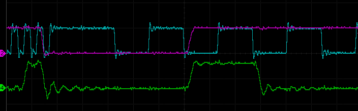
When I looked at the clock signal and IORQ signals on my oscilloscope - I was very surprised to see the clock speed did not seem to slow down every time the CPU issued an IORQ request - I struggled to believe my eyes - how did this not cause reliability issues? I can only assume it was infrequent enough to not manifest in my specific hardware and testing.
It seems on close inspection, when the Z80 is doing an IORQ write, the duration of the IORQ is sometimes too short for the clock slow down system to activate. Reads seem to always trigger the slow down.
Lets have a look at some traces of the situation:
Despite not observing any reliability issues, I thought it was best to fix this.
Now to understand the cause, we need to dig a little into the design. In the Turbo CPU module there are 3 main logic systems that work together.
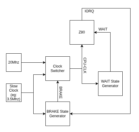
Now the 2 PLDs mentioned need to have their own clock signals to drive their logic. The WAIT State Generator is driven by the current active CPU clock. So it might be the slow or fast clock - depending on the current active speed. The BRAKE State Generator is driven by the SLOW clock always.
The problem arises when the CPU is running at its high speed and generates its IORQ signal. Given the BRAKE State Generator is driven by the slower clock, it will take a bit of time before it fully latches the BRAKE signal. And sometimes the timing and phase difference of the two clocks would mean that the BRAKE signal does not get latched before the CPU has finished its IORQ operation - thus it never switches to the slow clock speed for the required 31 clock ticks. (At least, thats what I think is happening!)
The best fix, that does not not require any hardware changes, is to update the WAIT State Generator to produce an additional WAIT state for IORQ requests. This change will extend the time of the IORQ periods slightly, enabling the BRAKE State Generator to respond in time.
In the original PLD code, there is the following bit of logic, that determines when a WAIT signal is to be generated.
MR = (MODE_NORMAL & MREQ & !RFSH & M1)
   # (MODE_MIDDLE & MREQ & !RFSH)
   # (MODE_FAST & MREQ & !RFSH);
This code was changed, as below, to now also generate a signal WAIT state when an IORQ operation is requested.
MR = (MODE_NORMAL & MREQ & !RFSH & M1)
   # (MODE_MIDDLE & MREQ & !RFSH)
   # (MODE_FAST & MREQ & !RFSH)
   # (!MODE_NORMAL & IORQ);
# is OR
& is AND
MODE_XXX is the position of the slider switch
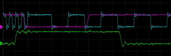
A simple fix. The following capture from my scope, shows the CPU clock rate (in blue), transitioning to the slow rate, when the IORQ (purple) trace goes active low. And it now always seems to correctly transition.
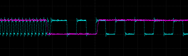
BLUE TRACE - CPU CLOCK
PURPLE TRACE - IORQ REQUEST
But I still could’t overclock the system beyond the 20Mhz rate – I did eventually - but will leave it to the next post to describe how.
 Store
Store