OK. So now back to my attempt to overclock the CPU beyond the 20Mhz rate.
As mentioned previously, any attempt to run the Turbo CPU module at anything above 20Mhz seemed to not work. I was fairly certain that all components of the system were capable of running at least a little higher.
I do not own a clock generator - I just replace the clock oscillator - I only have a set number of oscillators I can try - 20Mhz, 24Mhz, 25Mhz and a 32Mhz. I did not expect it would work at 32Mhz. But I would expect 24 and 25 should work reliably.
Well first thing I did was to review the PLD code I had written - and clean it up a bit. I refactored the Wait State Generator code. It was a little confusing and hacky. I did not change the Brake State Generator.
The logic required for WAIT generation it not really that complex - and remember this chip only needs to manage the WAIT state - it does not need to worry about the clock frequency slow-down or boost switching.
The chip needs to trigger 1 or more wait states under specific CPU states. The number of wait states and the specific CPU state are dependant on the position of the 3 way slider.
The slider’s three position are: NORMAL, MIDDLE and FAST.
NORMAL - In this mode, I need 1 WAIT state as per the MSX spec (sometimes simply called the M1 Wait State).
MIDDLE - In this mode, I want 3 WAIT states added for any memory read/write operations.
FAST - In this mode, I want just 1 WAIT state added for any memory read/write operation.
So to achieve this, it needs to detect the specific trigger scenario and set the WAIT signal active for the required number of clock cycles.
(It also needs to pass through the backplane’s WAIT signal to the CPU - in case external devices/modules request additional WAIT states)
So I simplified and made sure my logic was correct - and tried it out. And I had success - at 24Mhz and 25Mhz I got a booting system.
But then I tried at 20Mhz - and it would not boot - what tha?
At 16Mhz and many other frequencies it worked - but it would no longer work at 20Mhz - It sometimes would partially boot - but very quickly it would fail.
Today, I am unable to reproduce that specific issue - I don’t think I made a commit of the offending code - so can’t be sure what the logic was and I so am not able to capture specific traces.
My latest version works - so why complain Dean!
What I can demonstrate with scope traces, are comparison of two traces of the system attempting to operator at 25Mhz. One using my latest version of Wait State Generator and working, and one with the original version, not working.
Can you see a difference?
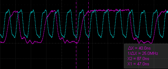
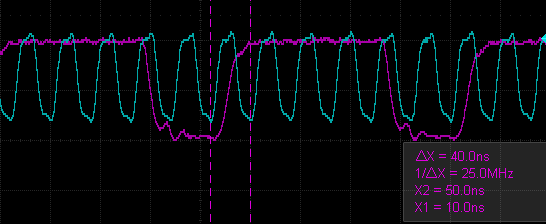
Can you see a difference? I cant! Maybe my scope has insufficient resolution/accuracy to show anything useful here. Maybe its something else - but I can’t see how. So I can only make a guess. Let me quote the Z80 manual.
..the CPU samples the WAIT line with the falling edge of the clock..
The WAIT signal rise does seem very close to the clock’s fall. Could there be an issue when the CPU attempts to sample a changing WAIT signal? Hmmm….
All I can be reasonable be sure of is:
Anyway, it seems to be operating at 25Mhz just fine now. I need to do a bit more testing to verify the reliability.
Nonetheless, as this point in time, it appears to be working - I am gonna leave it now.
No - thats enough - time to move on……..
I couldn’t help myself.
I conducted some experiments of timing and frequency, on my MSX build. I used the handy Z80Bench tool to get a measure the effective CPU speed.
And here are the results I got:
| Wait States | Frequency | Z80Bench Score |
|---|---|---|
| 0 W/S | 20Mhz | Did not boot |
| 1M W/S | 20Mhz | 17.68 |
| 1M W/S | 24Mhz | Did not boot |
| 1 W/S | 20Mhz | 15.32 |
| 1 W/S | 24Mhz | 18.39 |
| 1 W/S | 25Mhz | 19.15 |
Given the outcome of those experiements, I made an alternative Wait State Generator, that can run the system a little closer to its limits:
| Slider Mode | Wait States |
|---|---|
| NORMAL | Unchanged No Boost & 1M W/S for memory access |
| MIDDLE | Turbo Boost Enabled & 1 W/S for memory access |
| FAST | Turbo Boost Enabled & 1M W/S for memory access |
Now thats enough Dean - Cats are demanding their dinner!
 Store
Store