Code: DB315
A 13 slot RCBus 80 way backplane for RC2014 or RCBus Modules. Well suited for the full compliment of Stegosaur MSX and Green Modules.
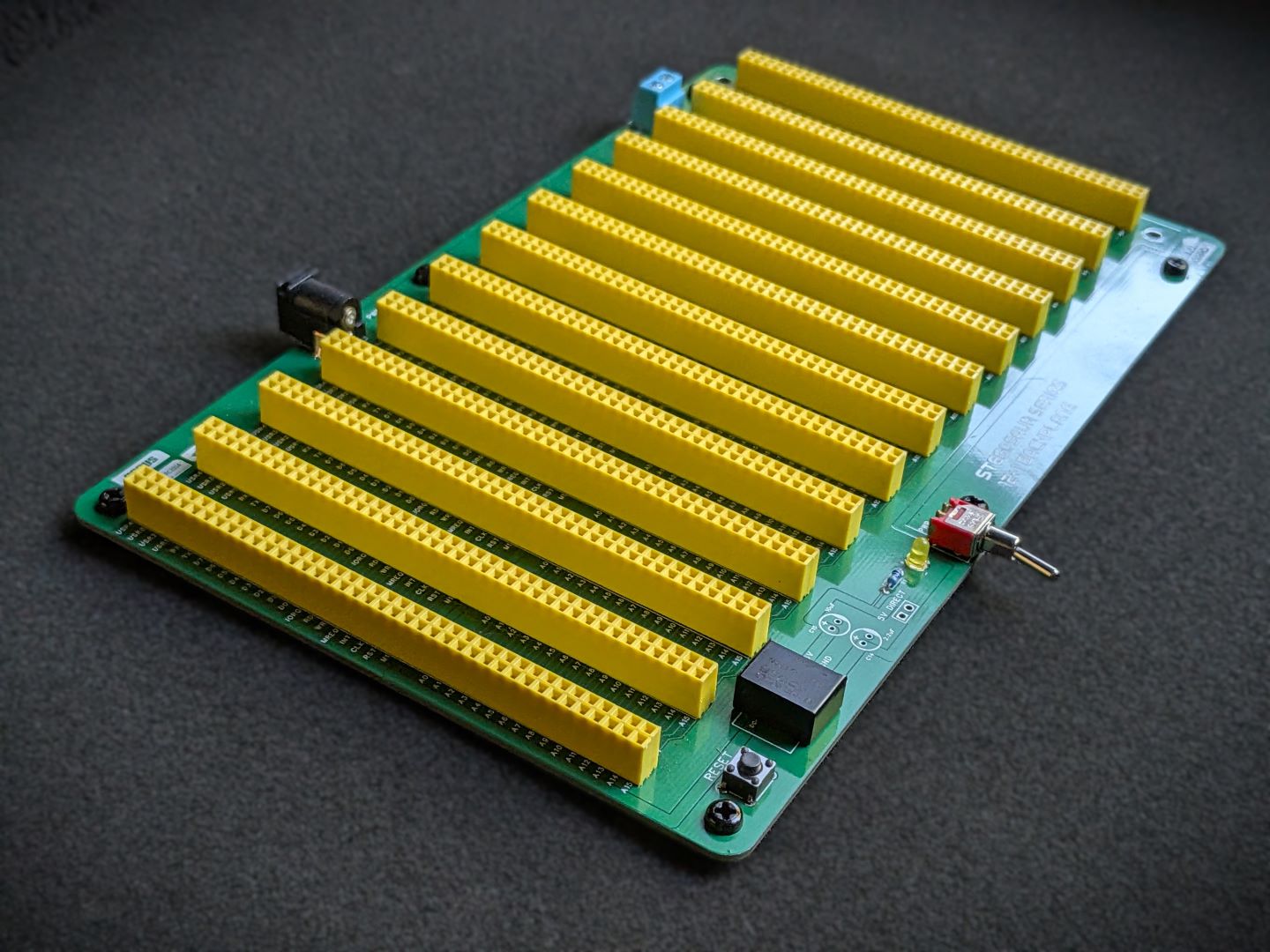
The backplane is an alternative to the Yellow MSX 12+1 Backplane.
The 13th slot is offset slightly from the rest of the slots, to allow for connecting the MSX Cartridge slot extension***
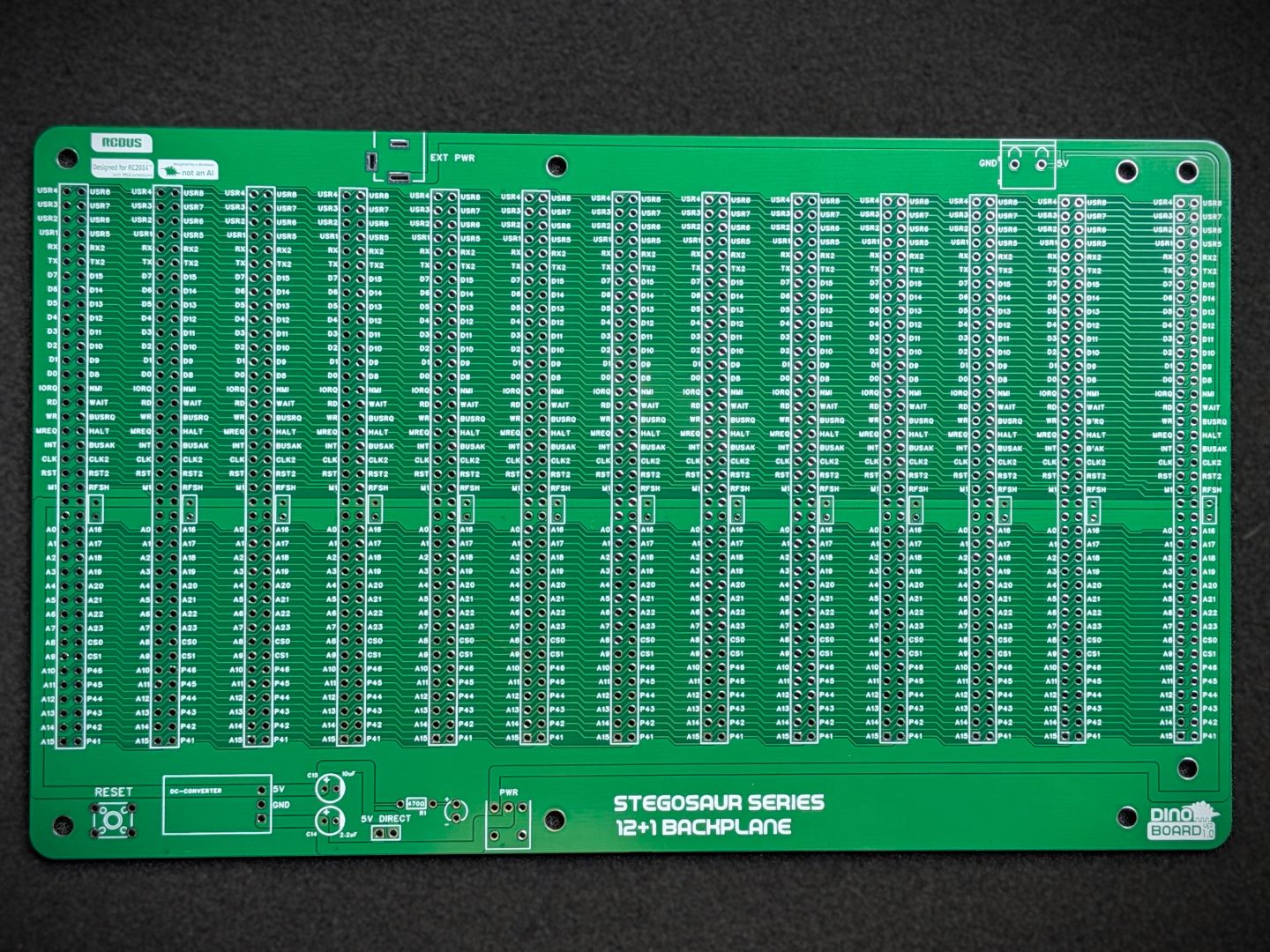 PCB Front |
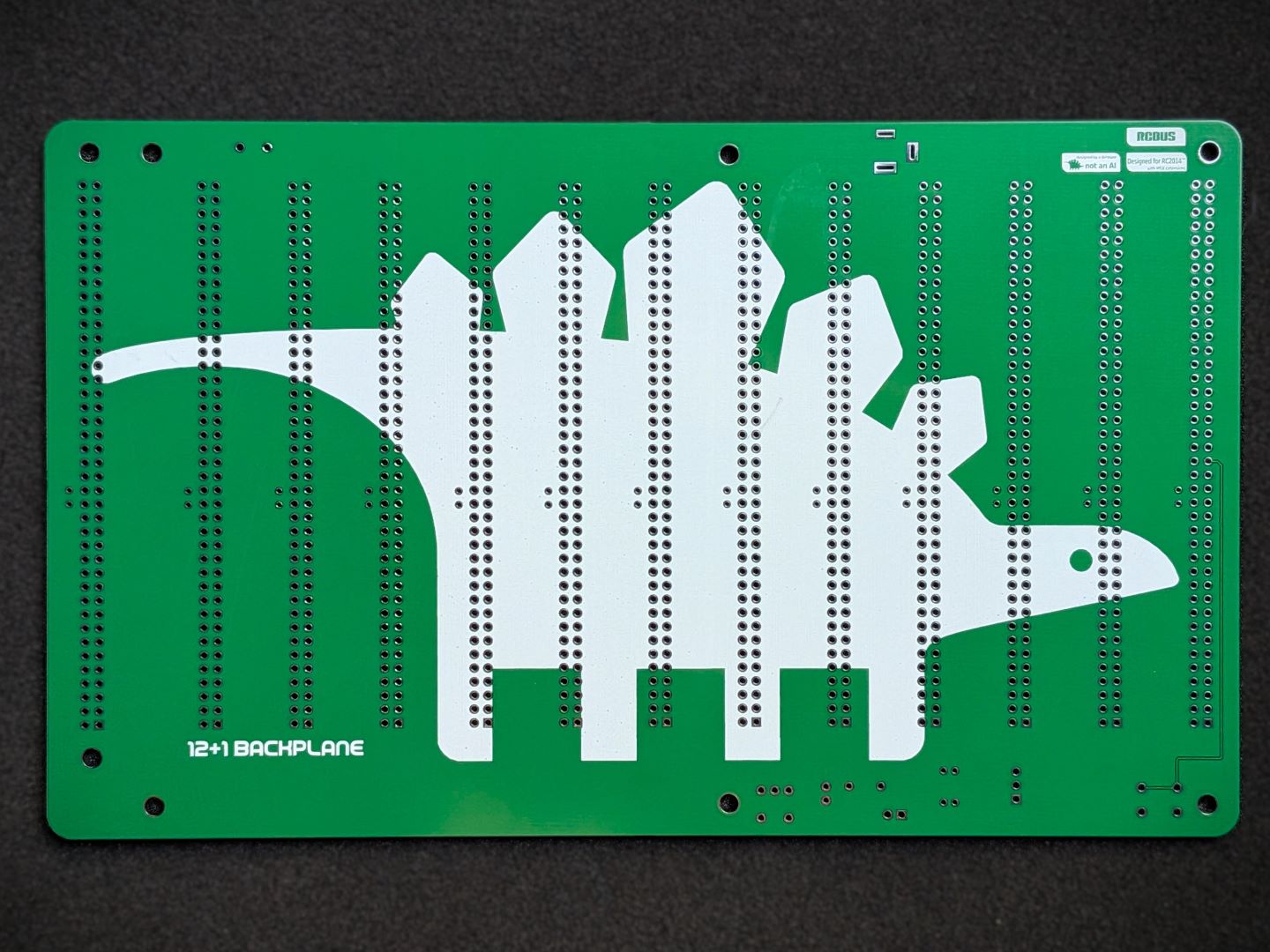 PCB Back |
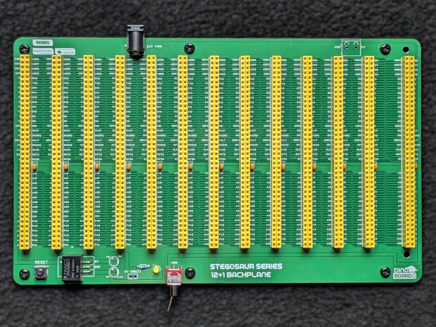 PCB Assembled |
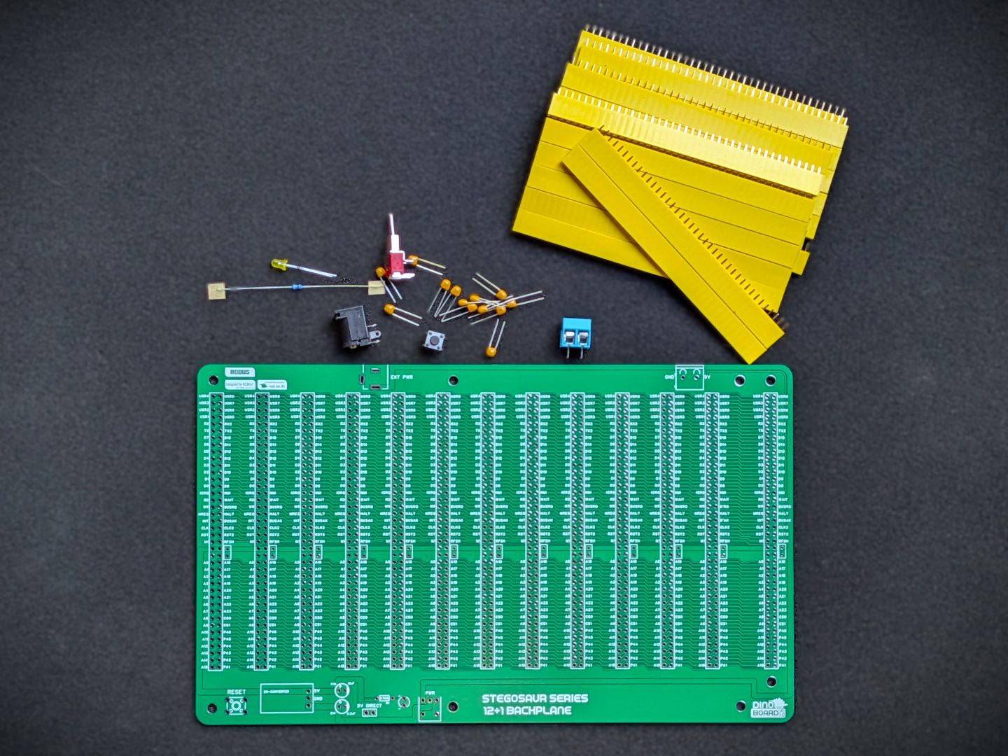 Main Parts |
Assembled |
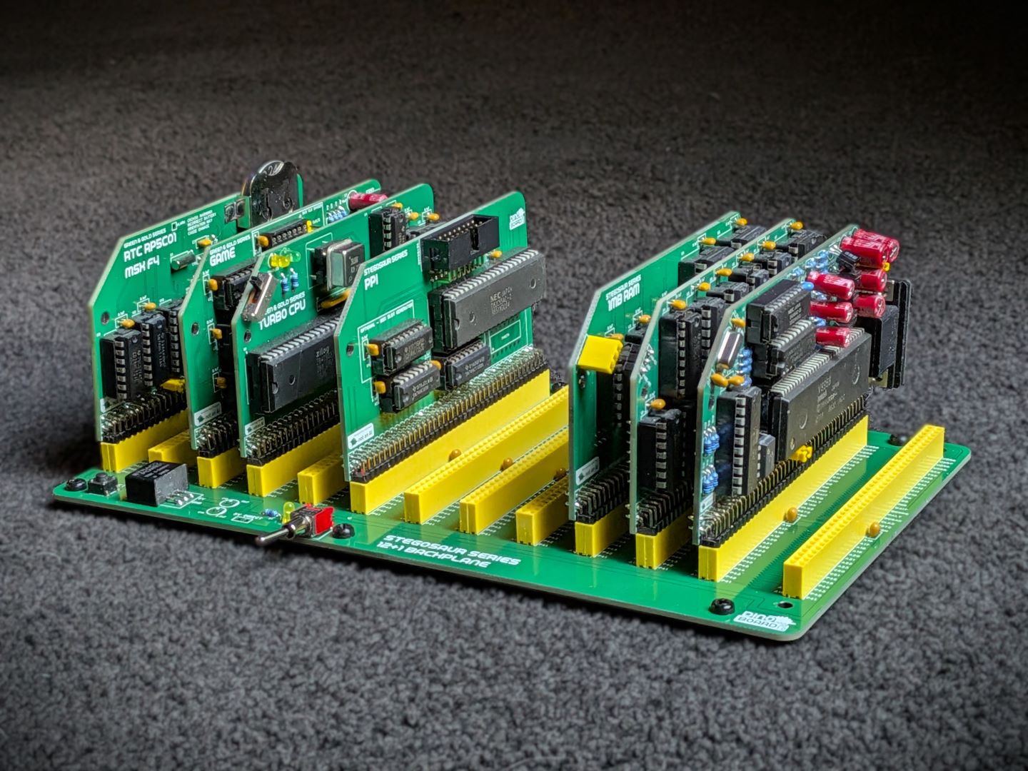 Assembled with some modules |
* Self Source Reference are supplied as a guide only. Please double check, in case of typo or errors in listing.
| Count | Name | Self Sourcing* |
|---|---|---|
| 26 | 40 Way SIL Socket* | |
| 13 | 0.1uF Ceramic Capacitors | Mouser: 594-K104K10X7RF53L2 DigiKey: BC5137-ND |
| 1 | 2.1mm Power Jack | Mouser: 490-PJ-002B DigiKey: CP-002B-ND |
| 1 | Tactile Switch | Mouser: 506-FSM4JH DigiKey: CP-002B-ND |
| 1 | SPDT Toggle Switch | Mouser: 612-200MSP1T1B2M6QE |
| 1 | 2 Way Screw Terminal | Mouser: 490-TB001-500-02BE |
| 1 | 470 Ω (3.4mm) | |
| 1 | 3mm LEDs |
| Count | Name | Self Sourcing* |
|---|---|---|
| 1 | Optional ~12V to 5DC Converter | Mouser: 919-R-78K5.0-2.0L DigiKey: 945-R-78K5.0-2.0L-ND DigiKey: 1589-1465-ND |
The full kits includes everything you need (PCB, capacitors, IC sockets, connectors, and the ICs).
The optional 5VDC converter, as with all parts, may be supplied with an alternative of similar specifications.
Please note that mounting stand-offs are not supplied.
This backplane requires modules. Any compatible RC2014/RCBus module can operate on this backplane.
This backplane works much like many other RC2014/RCBus backplanes. Provide an input voltage that is appropriate for the installed 5VDC Converter (typically 12V). Note the polarity of the power supply connector - the inner pin of the DC Barrel Connector is positive and the outer shield is ground.
The 5V DC converter optionally supplied is rated at 5V @ 2 Amps.
| Description | Yellow MSX Version | Green Stegosaur Version |
|---|---|---|
| Colour | Yellow | Green |
| On board LEDs | 12 x 5V yellow 5mm LEDs | Single 3mm power LED |
Generally, you want to solder items from lowest height to largest height. Review the components you need to solder, and note their progressive heights.
Please note the following specific points regarding this module:
There are a lot of headers. Pay close attention to their alignment, ensure square and flush with each other. If using a dual colour combinations of headers, keep the colours coordinated and consistent. Perhaps a black SIP for the left side and the coloured SIP for the right side.
Capacitors C10 and C11 are typically not required. Footprint is provided if additional DC filter required/desired.
Pay attention to the required correct orientation of the converter.
You can choose to power your backplane with a direct 5V power supply.
For bypassing, do not install the on-board converter and short the 5V Direct jumper and supply a good 5V power to the barrel or via the 2 way terminal block. You typically needs at least 1 to 1.5 Amp. 2 Amp is recommended.
Please note that this is a kit, produced by a non-expert (me) for hackers, DIYers’ and retro lovers, to tinker with. Please exercise caution and follow good safety practices. You will be working with sharp knives, a hot soldering iron, and small metal components. Be mindful of the risks involved in the build process. I will do my best to answer any questions you may have.
This kit is provided as-is, with no guarantees or warranties. By assembling and using this kit, you acknowledge that you do so at your own risk.
 Store
Store