Code: DB306
Optional Controller Expansion: DB307
Experience retro sounds with the YM2149 sound and optional expansion game controller module. This module provides MSX-compatible sound and controller support (joysticks, game pads, etc.) for your RC2014/RCBus system. It is also compatible with RomWBW sound applications.
Here is a short video of the module playing music on a RomWBW booted system.
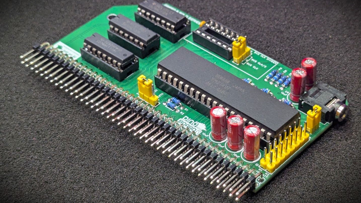
 YM2149 Build |
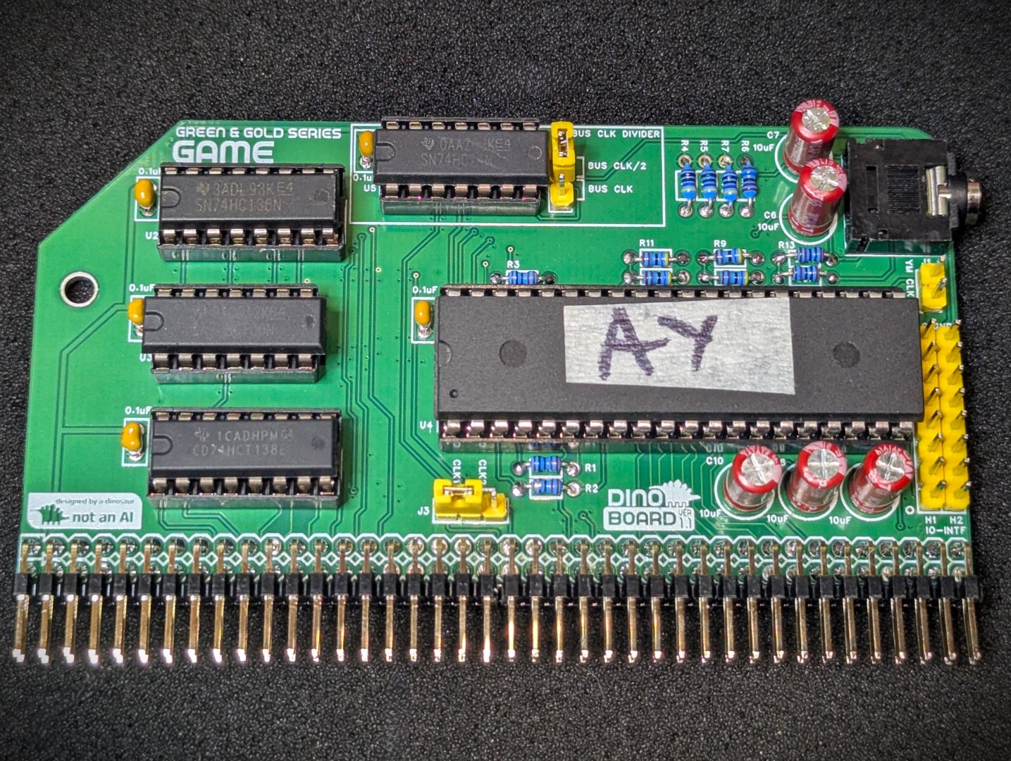 AY-3-8190 Build |
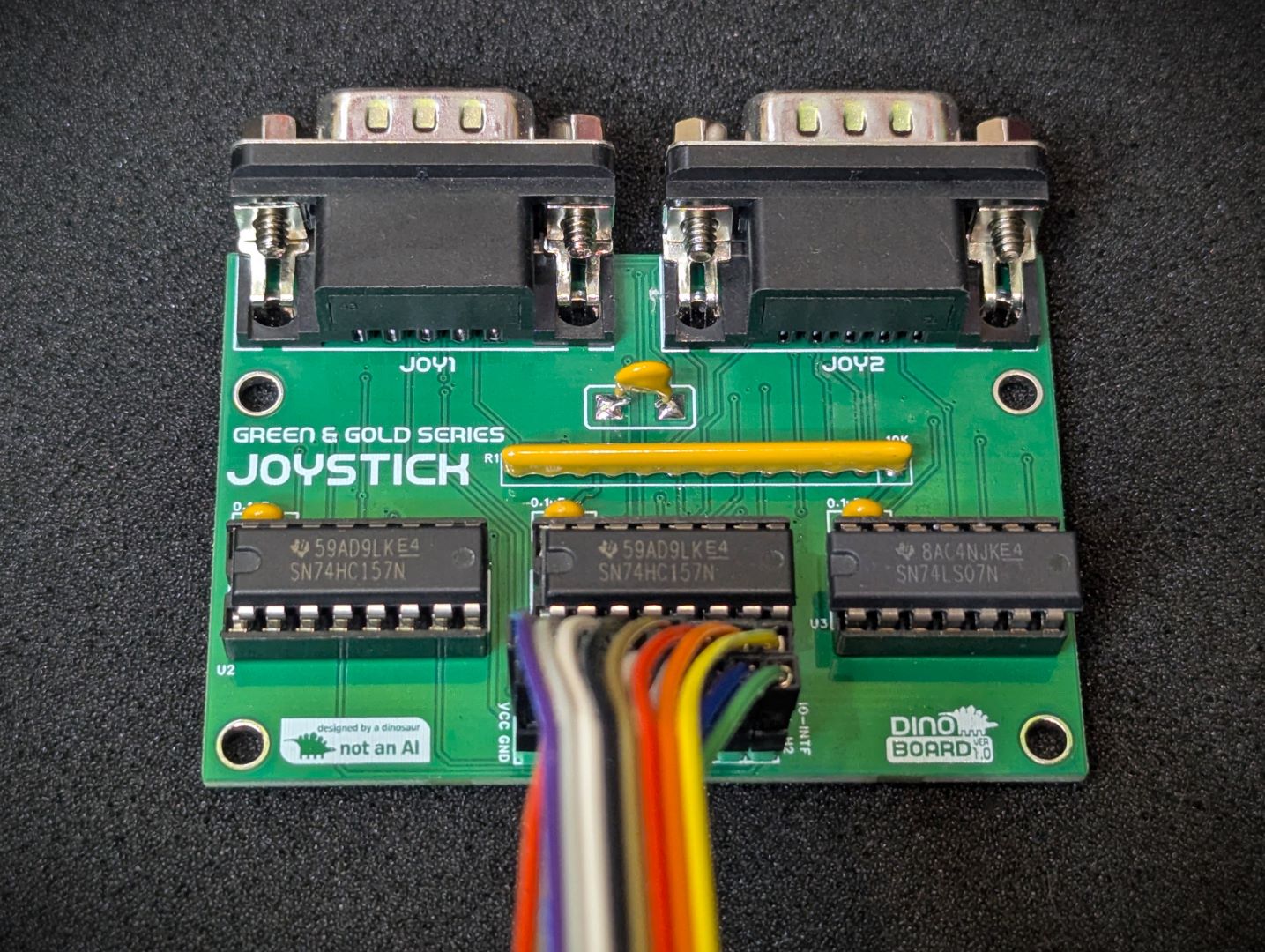 Game Controller Expansion Build |
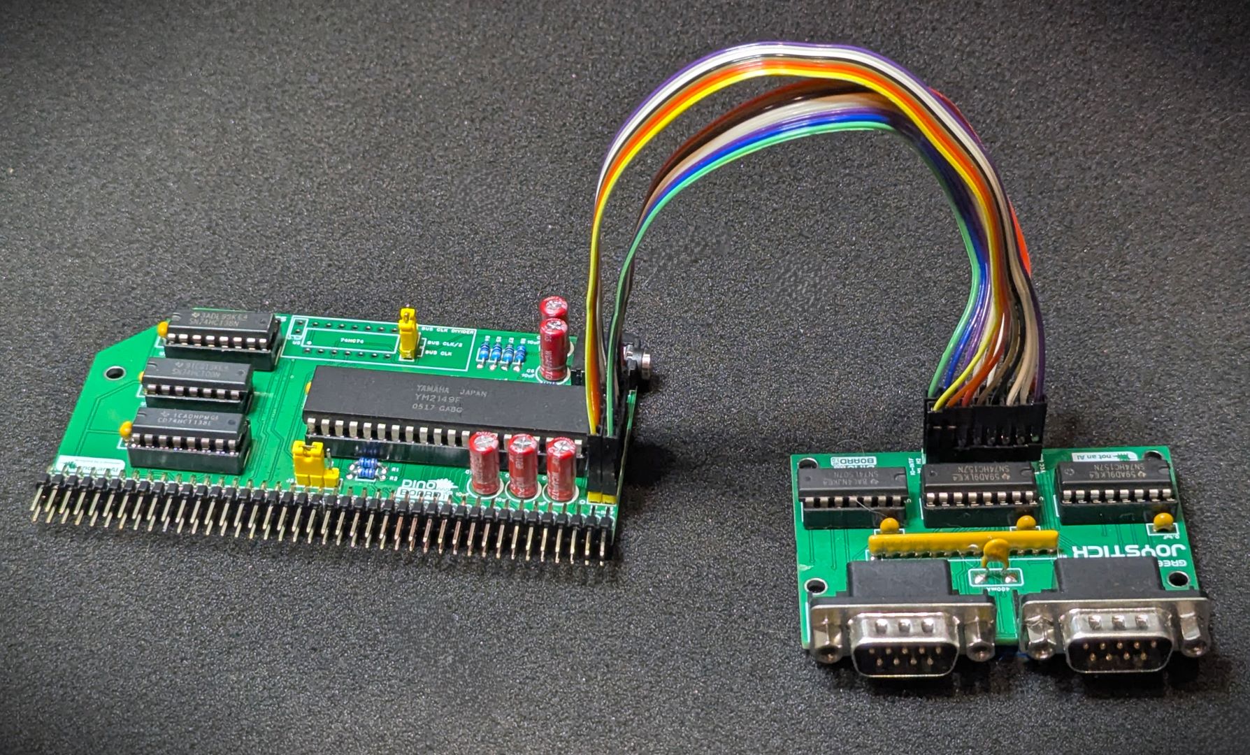 Game Controller Connected |
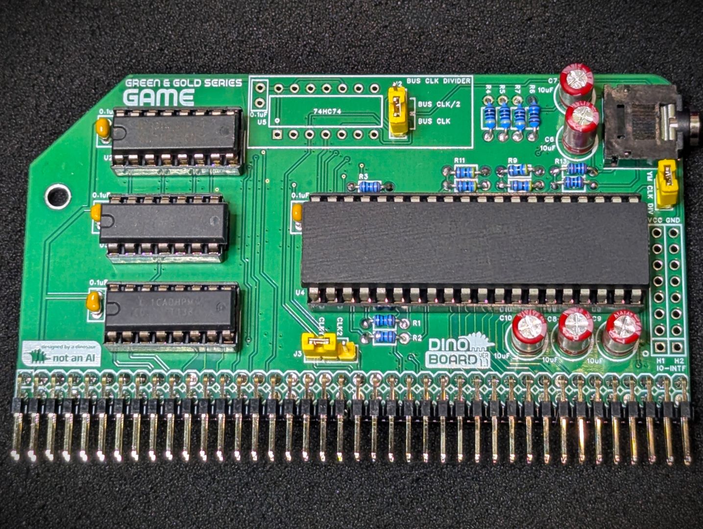
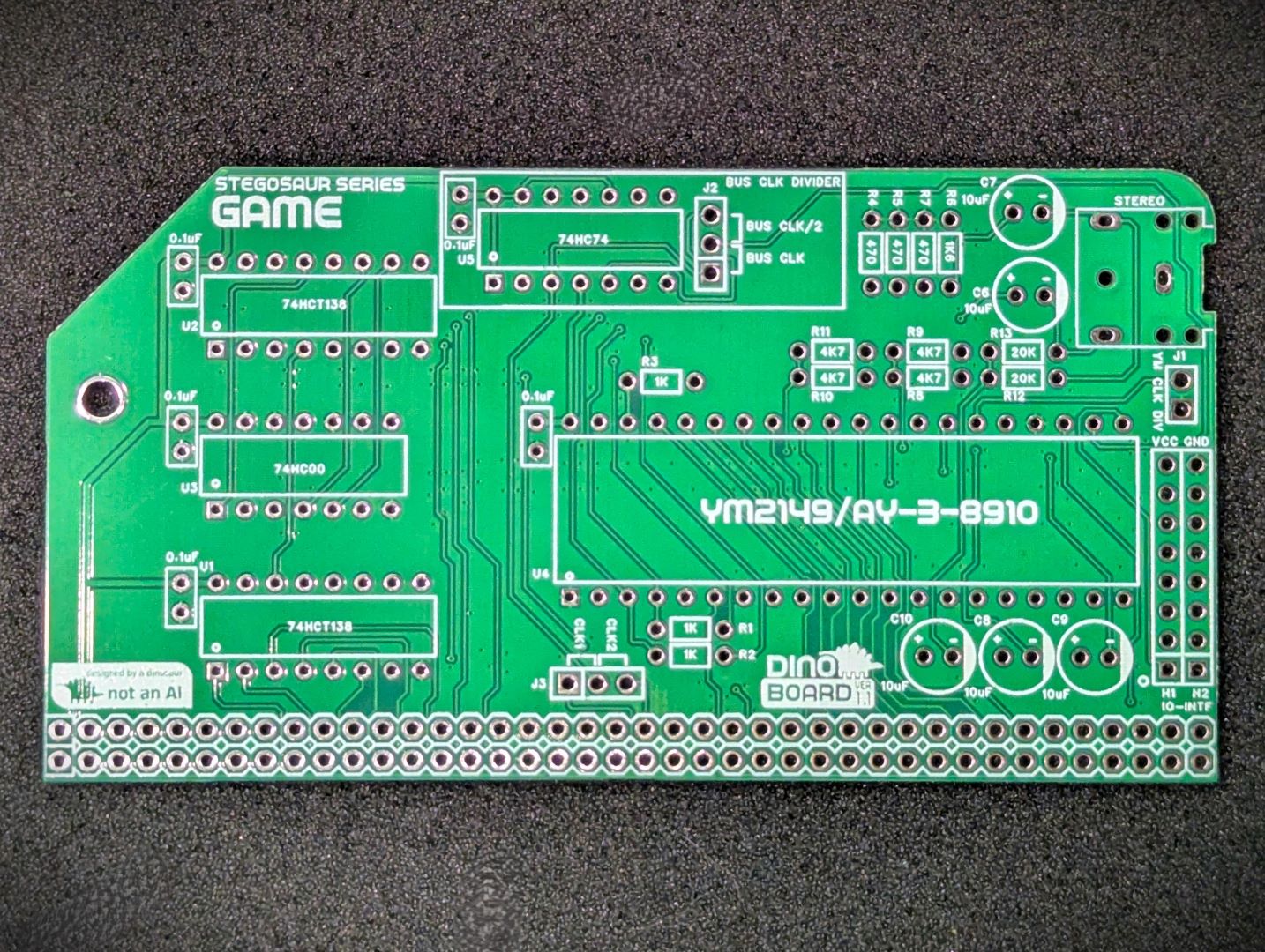 Main PCB Front |
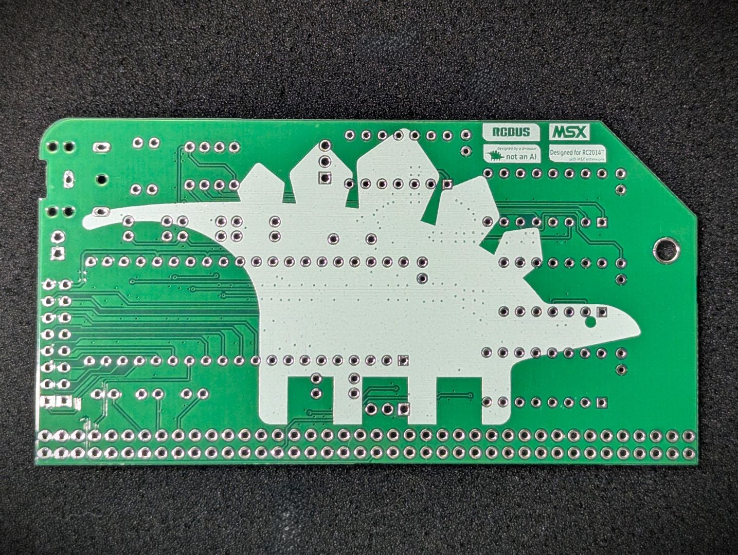 Main PCB Back |
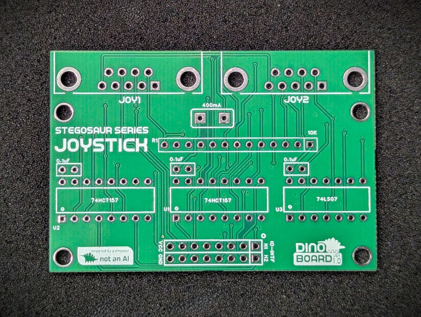 Controller Expansion PCB Front |
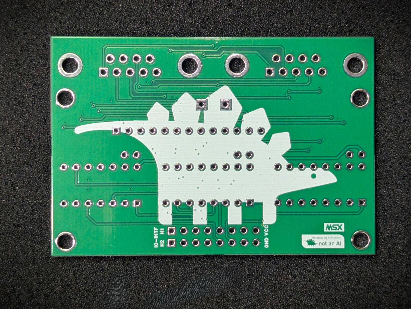 Controller Expansion PCB Back |
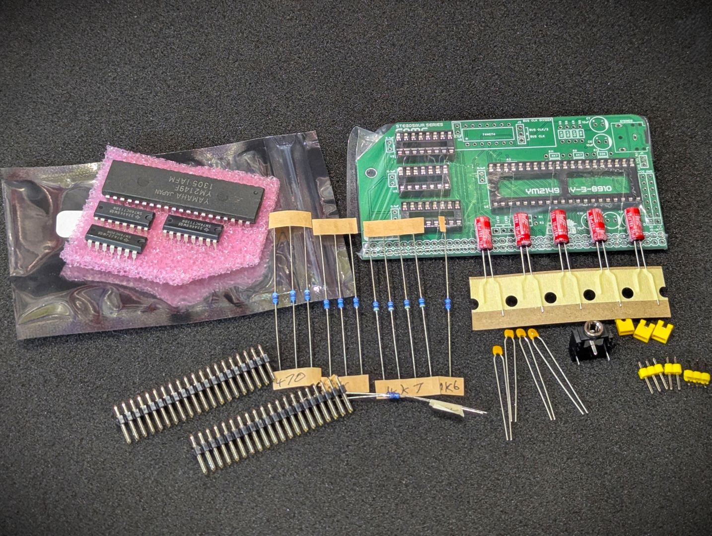 Main kit parts |
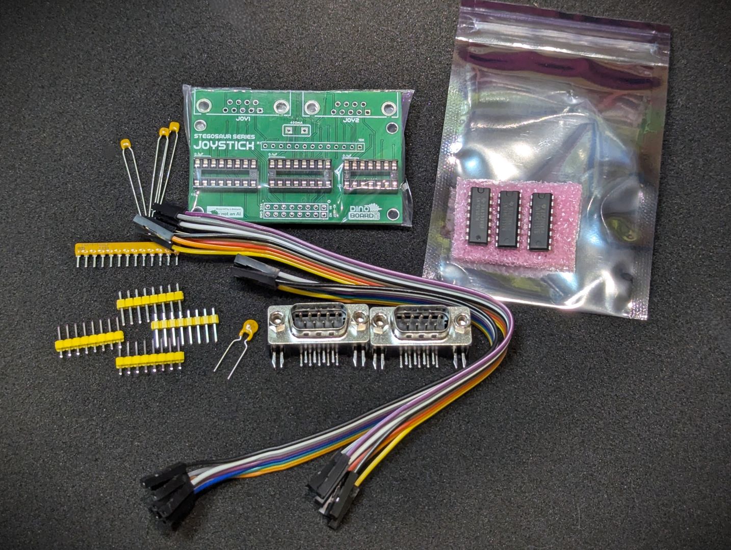 Optional Controller Parts Optional Controller Parts |
* Self Source Reference are supplied as a guide only. Please double check, in case of typo or errors in listing.
| Count | Name | Self Sourcing* |
|---|---|---|
| 4 | 0.1uF Ceramic Capacitors | Mouser: 594-K104K10X7RF53L2 DigiKey: BC5137-ND |
| 5 | 10uF | |
| 1 | 3.5 Audio Socket | Mouser: 490-SJ1-3523N DigiKey: CP1-3523N-ND |
| 1 | 10k Ω Bussed x 12 | |
| 3 | 1k Ω (3.4mm) | |
| 1 | 1k6 Ω (3.4mm) | |
| 4 | 4k7 Ω (3.4mm) | |
| 2 | 20k Ω (3.4mm) | |
| 1 | 470 Ω (3.4mm) | |
| 2 | 74HCT138 | |
| 1 | 74HC00 | |
| 2 | Headers 1x3 | |
| 1 | Headers 1x2 | |
| 3 | Shunt 1x2 | |
| 2 | Right Angle 2x20 Header | Mouser: 649-68020-140HLF DigiKey: 2057-PH2RA-40-UA-ND |
| 1 | 14 POS IC SOCKET | Mouser: 571-1-2199298-3 DigiKey: 2057-ICS-314-T-ND |
| 2 | 16 POS IC SOCKET | Mouser: 571-1-2199298-4 DigiKey: 2057-ICS-316-T-ND |
| 1 | 40 POS IC SOCKET | Mouser: 571-1-2199299-5 DigiKey: 2057-ICS-640-T-ND |
| 1 | PCB |
| Count | Name | Self Sourcing* |
|---|---|---|
| 1 | 0.1uF Ceramic Capacitors | Mouser: 594-K104K10X7RF53L2 DigiKey: BC5137-ND |
| 1 | 74HC74 | |
| 1 | 14 POS IC SOCKET | Mouser: 571-1-2199298-3 DigiKey: 2057-ICS-314-T-ND |
| Count | Name | Self Sourcing* |
|---|---|---|
| 3 | 0.1uF Ceramic Capacitors | Mouser: 594-K104K10X7RF53L2 DigiKey: BC5137-ND |
| 1 | 400mA Fuse | Mouser: 530-0ZRG0075FF1E DigiKey: 5923-0ZRG0075FF1E-ND |
| 1 | 9-PIN DSUB CONNECTOR | Mouser: 737-DE09-PL-25 DigiKey: 2057-DE09-PL-25-ND |
| 1 | 10k Ω Bussed x 12 resistor | Mouser: 652-4613X-1LF-10K DigiKey: 652-4613X-1LF-10K |
| 1 | 74LS07 | |
| 2 | 74HCT157 | |
| 1 | 14 POS IC SOCKET | Mouser: 571-1-2199298-3 DigiKey: 2057-ICS-314-T-ND |
| 2 | 16 POS IC SOCKET | Mouser: 571-1-2199298-4 DigiKey: 2057-ICS-316-T-ND |
| 16 | Jumper wires - female to female | |
| 2 | HEADERS 2x8 | |
| 1 | PCB |
| Count | Name | Self Sourcing* |
|---|---|---|
| 1 | YM2149 |
The YM2149 is tested to confirm the chip’s function.
| Count | Name | Self Sourcing* |
|---|---|---|
| 1 | AY-3-8910 |
The AY-3-8910 is tested to confirm the chip’s function. It may have been incorrectly marked as a YM2149. Requires the Optional AY Support for the external clock divider circuit.
These 2 sounds chips are almost identical and will for the most part produce identical sound output. Due to the 2nd hand nature of these chips, the AY-3-8910 may have been re-marked as a YM2149. See https://maidavale.org/blog/ay-ym-differences/ for a thorough description of the differences.
| Feature | YM2149 | AY-3-8910 |
|---|---|---|
| hardware volume envelope | 5 bits | 4 bits |
| On chip clock divider | Yes | No |
| Register Reads | Yes | Always 0 |
This base kit includes the usual main components (PCB, capacitors, IC sockets, connectors, and the ICs)
A tested YM2149 can be optionally included or you can source your own.
The optional Expansion Module includes parts need to assemble it and a set of 16 connecting jumpers.
The optional on-board clock divider parts can also be included is desired. See the Jumper section below to determine if you need the divider installed.
This module can work in a standard RC2014/RCBus RomWBW bootable system, or a MSX configured bootable system.
You need an external powered speaker to hear the audio. It is recommended to use stereo speakers to enjoy the stereo mix.
The connecting 3.5mm cable must be the 3 pole stereo type.
The tune.com cp/m distributed with RomWBW works just fine with the board.
Standard MSX port mapping.
| Port | range | Description |
|---|---|---|
| #A0 | (write) | Register write port |
| #A1 | (write) | Value write port |
| #A2 | (read) | Value read port |
The following table describes the registers of the PSG:
| Register(s) | Description |
|---|---|
| 0-5 | Tone generator control |
| 6 | Noise generator control |
| 7 | Mixer control-I/O enable. Important note: bit 6 must be 0, and bit 7 must be 1. |
| 8-10 | Amplitude control |
| 11-13 | Envelope generator control |
| 14-15 | I/O ports A & B |
The following jumpers are used to select the clock frequency used by the audio chips (YM2149 or the optional AY-3-8910). Both chips needs a clock frequency of 1.79Mhz (or close to it). The clock is sourced from the RC2014/RCBus clock lanes as per J3.
The YM2149 has support for an onboard clock divider.
| CLK1 Frequency | Audio Chip Type | J1 | J2 | J3 | On-board clock divider needed |
|---|---|---|---|---|---|
| ~3.58Mhz | YM2149 | shorted | lower 2 pins shorted | 2 left pins shorted. | No |
| ~3.58Mhz | AY-3-8910 | not shorted | upper 2 pins shorted* | 2 left pins shorted. | Yes |
| ~3.69Mhz | YM2149 | shorted | lower 2 pins shorted | 2 left pins shorted. | No |
| ~3.69Mhz | AY-3-8910 | not shorted | upper 2 pins shorted* | 2 left pins shorted. | Yes |
| ~7.37Mhz | YM2149 | shorted | upper 2 pins shorted* | 2 left pins shorted. | Yes |
| CLK2 Frequency | Audio Chip Type | J1 | J2 | J3 | On-board clock divider needed |
|---|---|---|---|---|---|
| ~1.84Mhz | YM2149 | not shorted | lower 2 pins shorted | 2 right pins shorted. | No |
| ~1.84Mhz | AY-3-8910 | not shorted | lower 2 pins shorted | 2 right pins shorted. | No |
| ~3.69Mhz | YM2149 | shorted | lower 2 pins shorted | 2 right pins shorted. | No |
| ~3.69Mhz | AY-3-8910 | not shorted | upper 2 pins shorted* | 2 right pins shorted. | Yes |
| ~7.37Mhz | YM2149 | shorted | upper 2 pins shorted* | 2 right pins shorted. | Yes |
* U5 74HC74 must also be inserted.
When this jumper is shorted, the onboard clock divider of the YM2149 is enabled. For operation with an AY-3-8910 this jumper must not be shorted. The YM2149’s on-chip clock divider will halve the clock rate received by the chip. If the incoming clock rate is ~3.5Mhz, then use this jumper to divide it by 2 to get to the desired rate of ~1.79Mhz.
Optionally enable the on-board clock divider (if installed). If the 74HC74 is not installed, the lower 2 pins of J2 must be shorted.
Select the source of the clock signal used by the above jumpers that is ultimately supplied to the chip. For typical MSX configuration, this should be CLK1 (2 left pins shorted), as supplied by the Video Module.
| Description | Yellow MSX Version | Green Stegosaur Version |
|---|---|---|
| Clock Source | On board crystal @ 3.579545Mhz | External CLK1 or CLK2 of RC2014/RCBus |
| Audio Output | Mono | Stereo - (3 channels mixed into a stereo field) |
| Audio Output Connection | 3.5mm socket and 2 pin header | 3.5mm socket only |
| Game Controller Inputs | on main PCB | optional expansion breakout board |
| PCB Height | 8.0 cm | 5.5 cm |
| Support YM2149 | Yes | Yes |
| Support AY-3-8910 | Yes | Yes* |
| Backplane Requirement | 80 Way RCBus or RC2014 via external Jumpers | Wired permanently to 80 Way RCBus ‘User’ lanes (37-40, 77-80) |
| Colour | Yellow | Green |
* Optional external clock divider needed.
Generally, you want to solder items from lowest height to largest height. Review the components you need to solder, and note their progressive heights.
* Note the right angle headers are position correctly and lay flush and at right angle to the main PCB.
Please note the following specific points regarding this module:
If you only intend to operate with the YM2149 sound chip, you typically will not need U5 (74HC74) and its associated decoupling capacitor (0.1uF). But you do need to ensure J2 has the bottom two pins shorted - either by installing the 3 pin header and applying a shunt, or by simply soldering a wire between the lower 2 pins.
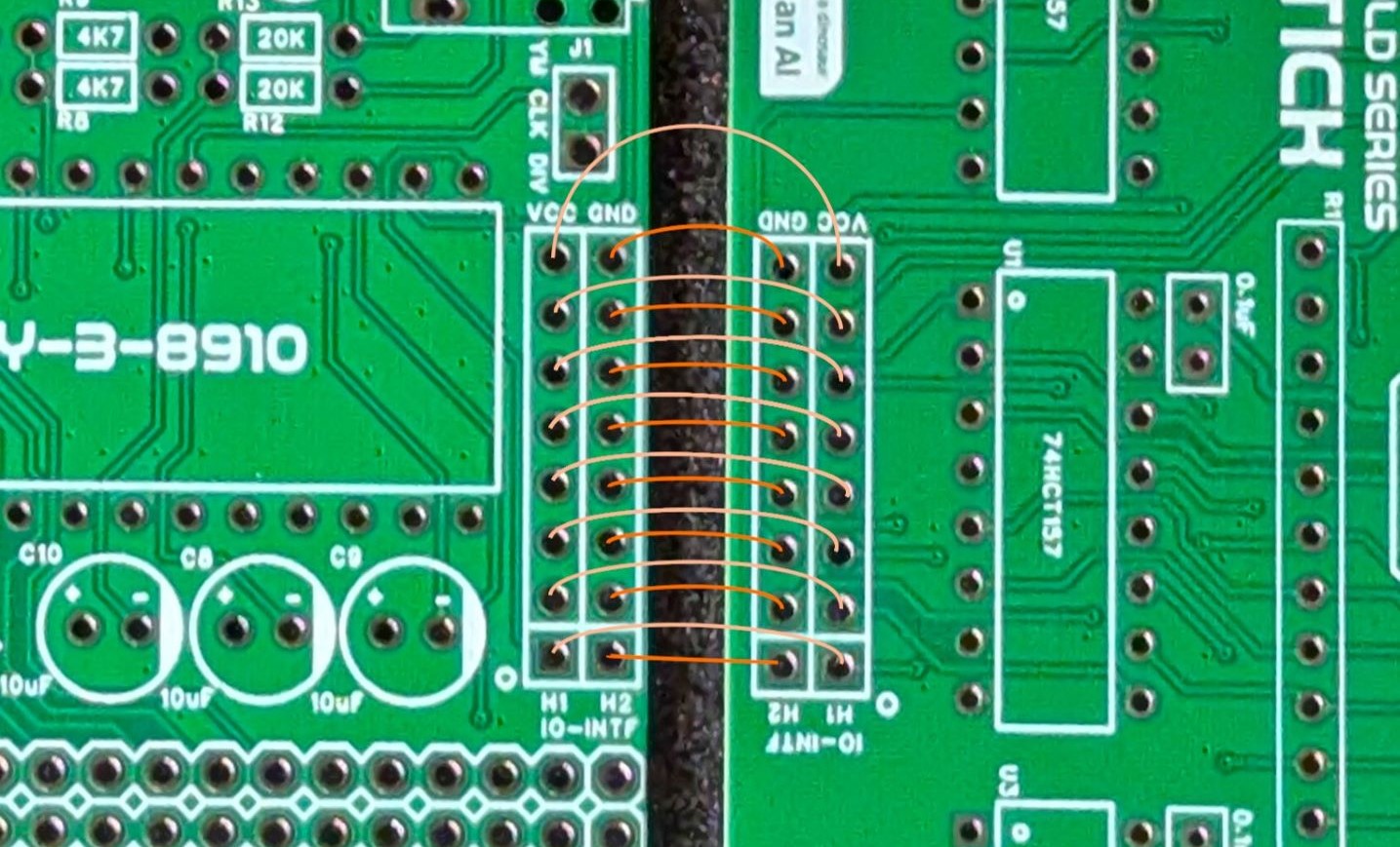
The optional controller expansion board, is connected via two set of 8 connecting jumper wires. As there is no 'key' to ensure the correct alignment of pins, between the main board and the controller board, its possible to inadvertently install the controller board incorrectly. Please ensure the GND and VCC pins are aligned across the two boards and connections are followed sequentially on down the headers, as shown in marked up image.
It is possible to inadvertently invert the order of individual connections - please double check you have jumpered all pins sequentially.
If you insert a ‘mono’ plug into the socket, you will create a short across ground and one of the channels. This module (unlike the yellow series), requires a stereo plug and associated amplifier.
Please note that this is a kit, produced by a non-expert (me) for hackers, DIYers’ and retro lovers, to tinker with. Please exercise caution and follow good safety practices. You will be working with sharp knives, a hot soldering iron, and small metal components. Be mindful of the risks involved in the build process. I will do my best to answer any questions you may have.
This kit is provided as-is, with no guarantees or warranties. By assembling and using this kit, you acknowledge that you do so at your own risk.
 Store
Store