
RAM: DB310
ROM: DB311
A full MSX Memory System. 512K of ROM boot code and support software and up to 1MB of paged RAM. With these modules, you can boot into various MSX bios (open source CBIOS, MSX-BIOS/BASIC).
The two modules work together to map in a 512K rom image for booting, and page in the RAM using specific MSX memory mapping techniques.
The 512K ROM image is mapped across a number opf MSX “slots” and “sub-slots” - enabling the storage of BIOS, Operating System and various applications and drivers.
The 2x512K RAM is mapped, using MSX’s memory page mapping, enabling compatible systems and applications the full use of the available RAM.
This module is designed for operation in conjunction with other MSX modules (CPU, GAME, RGB VIDEO, PPI & Keyboard)
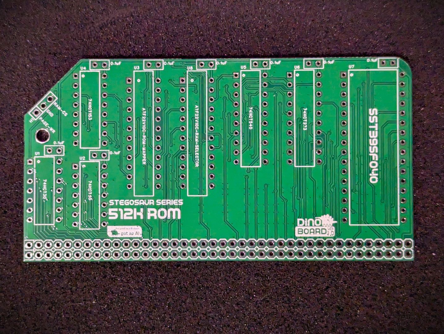 ROM PCB Front |
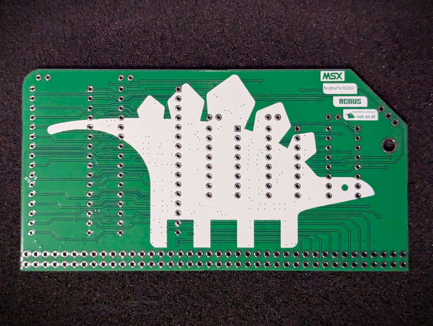
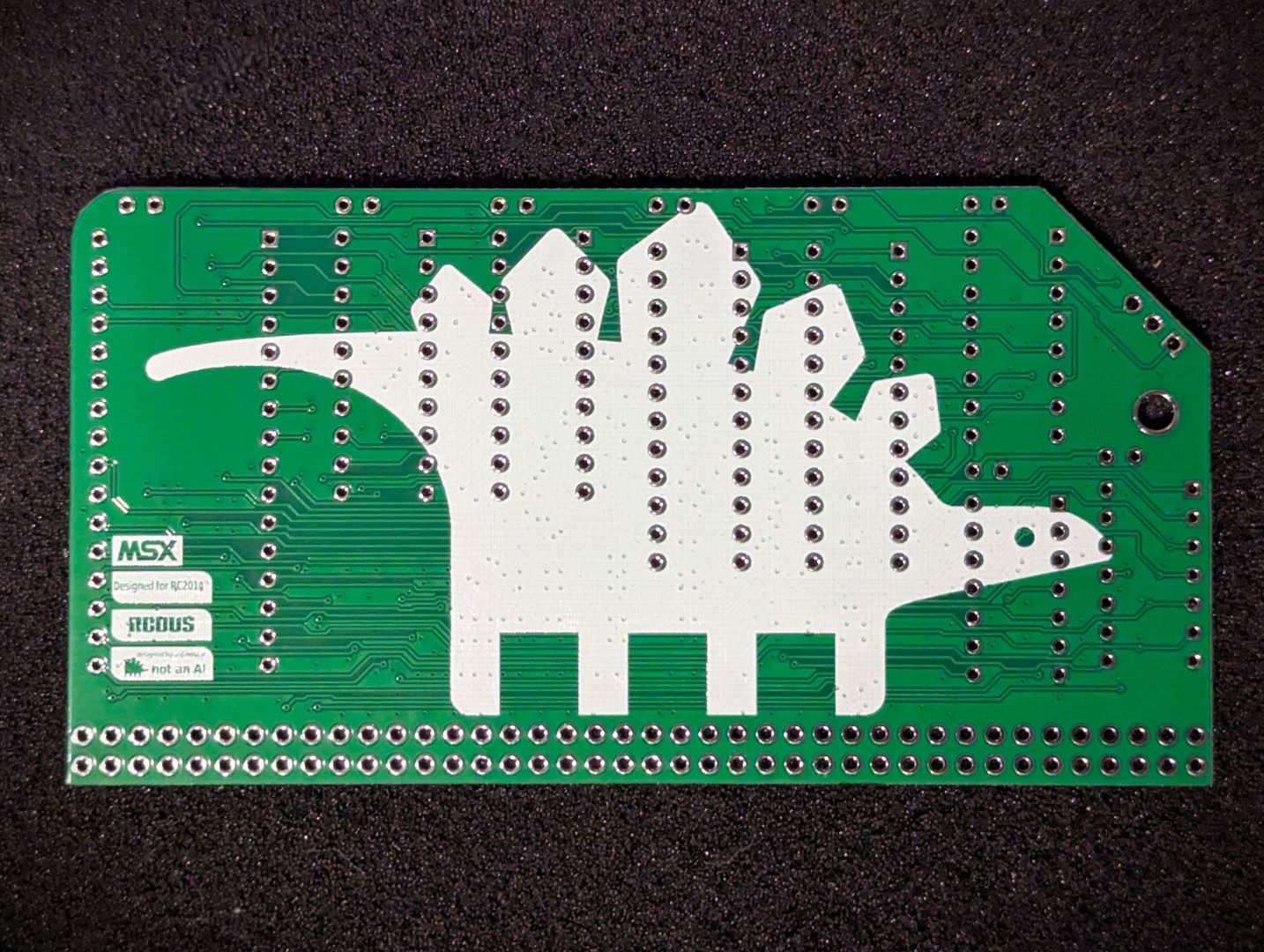 ROM PCB Back |
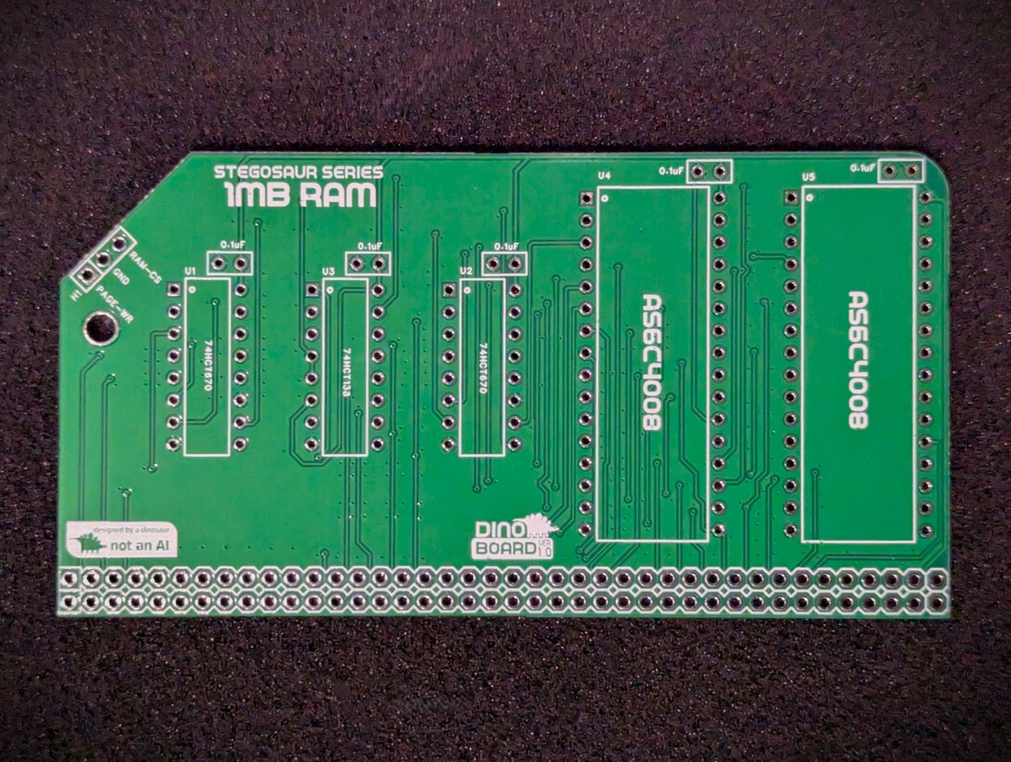 RAM PCB Front |
 RAM PCB Back |
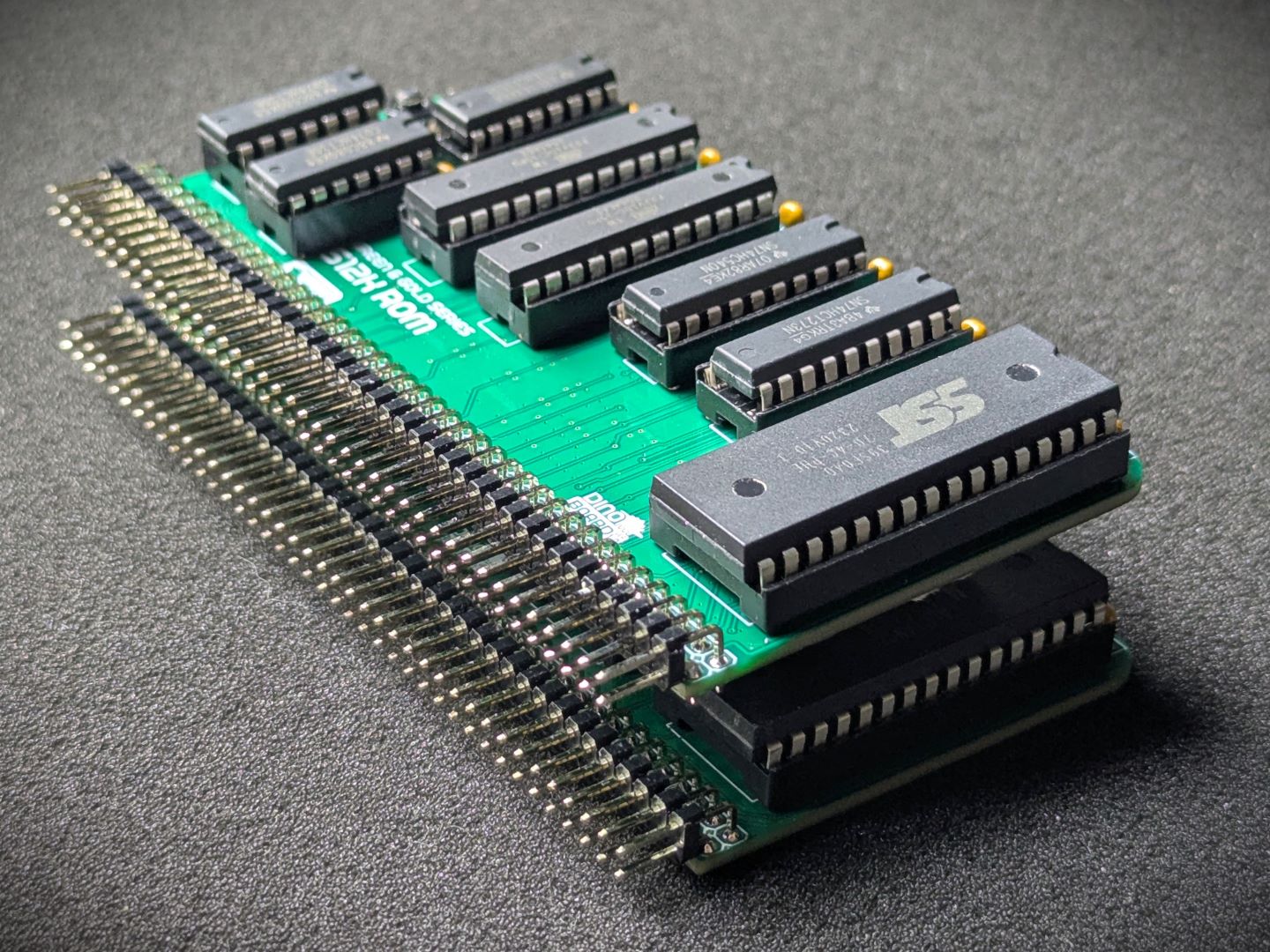
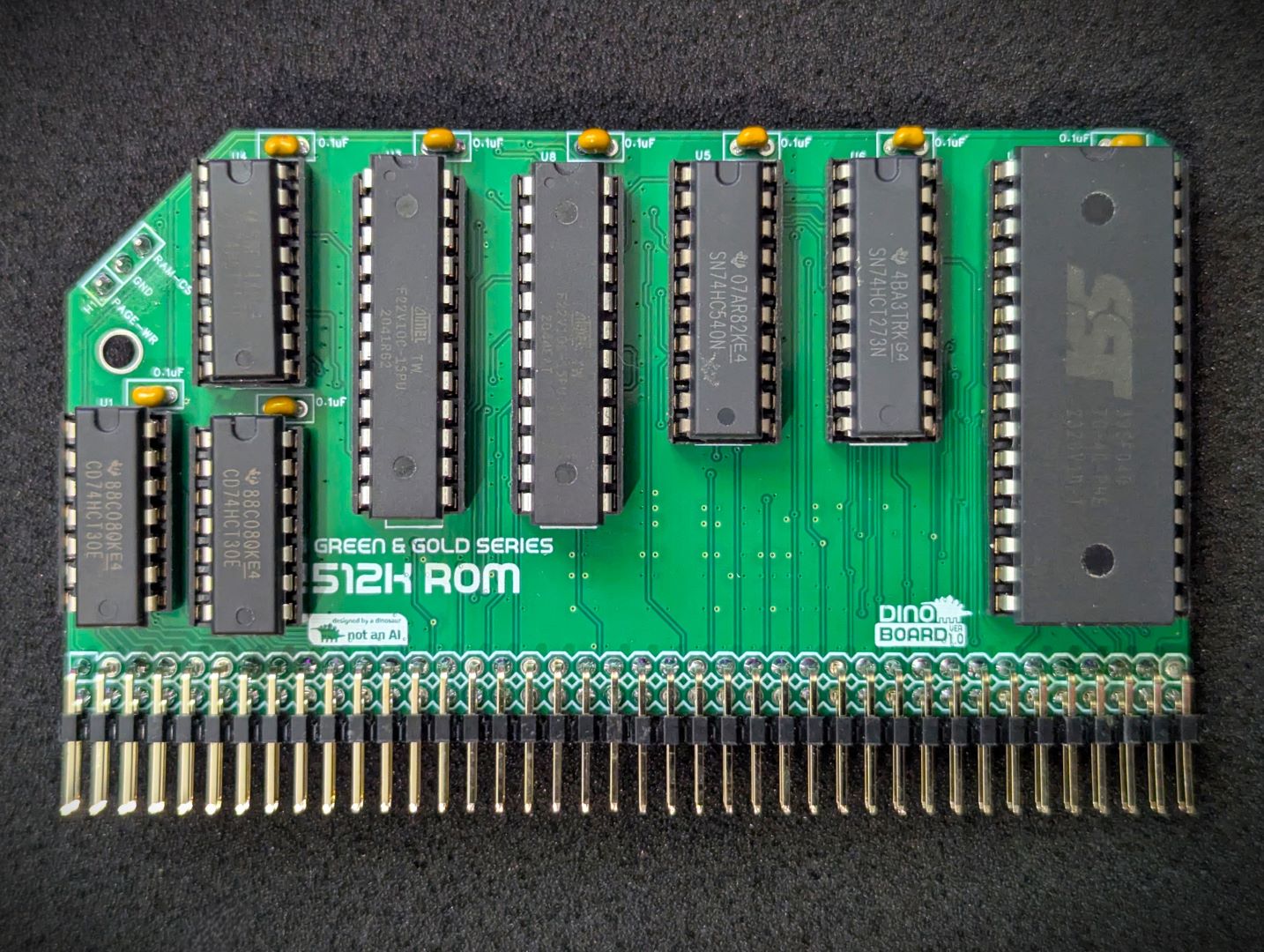 ROM Module Assembled |
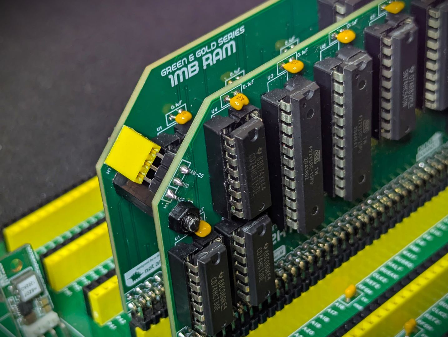
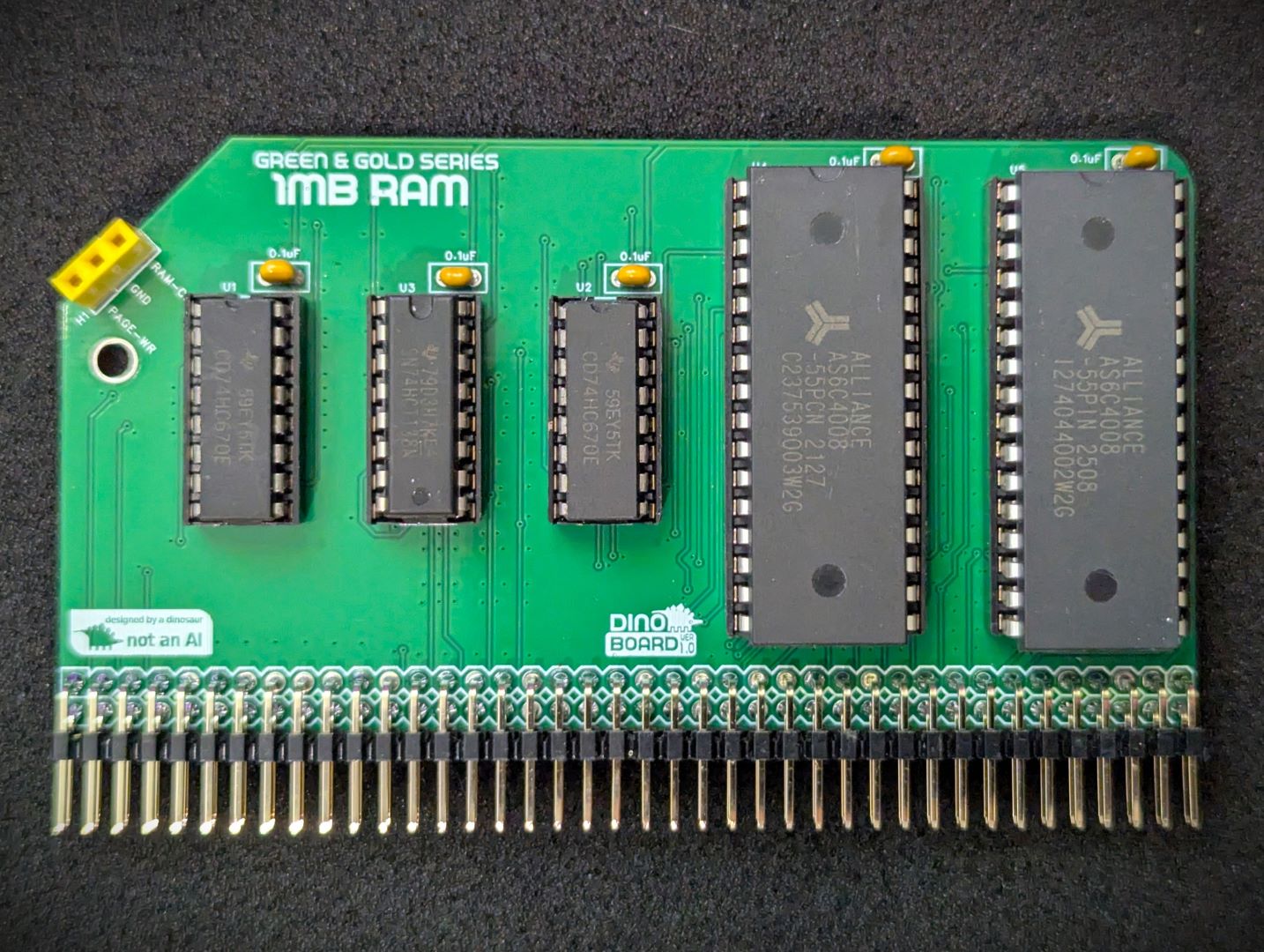 RAM Module Assembled |
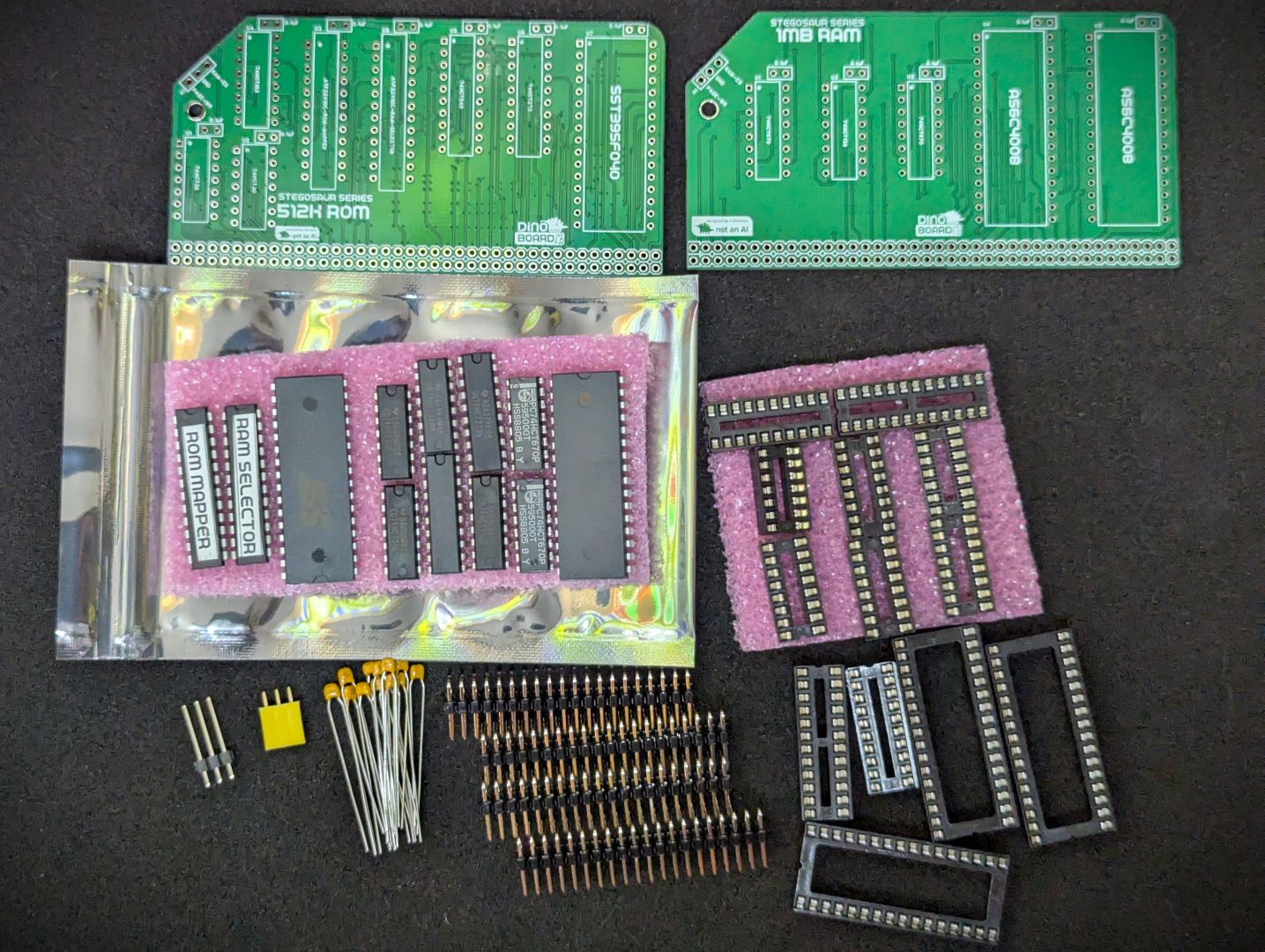 Base Kit Parts |
 ROM-RAM inter-board connection |
* Self Source Reference are supplied as a guide only. Please double check, in case of typo or errors in listing.
| Count | Name | Self Sourcing* |
|---|---|---|
| 13 | 0.1uF Ceramic Capacitors | Mouser: 594-K104K10X7RF53L2 DigiKey: BC5137-ND |
| 1 | 1x3 Header socket | |
| 1 | 1x3 Header plug (17mm) | |
| 1 | ATF22V10C-15PU (RAM SELECTOR) | |
| 1 | ATF22V10C-15PU (ROM-MAPPER) | |
| 1 | AS6C4008 | |
| 1 | SST39SF040 | |
| 2 | 74HCT30 | |
| 1 | 74HC138 | |
| 1 | 74HCT153 | |
| 1 | 74HCT273 | |
| 1 | 74HC540 | |
| 2 | 74HCT670 | |
| 4 | Right Angle 2x20 Header | Mouser: 649-68020-140HLF DigiKey: 2057-PH2RA-40-UA-ND |
| 2 | 14 POS IC SOCKET | Mouser: 571-1-2199298-3 DigiKey: 2057-ICS-314-T-ND |
| 4 | 16 POS IC SOCKET | Mouser: 571-1-2199298-4 DigiKey: 2057-ICS-316-T-ND |
| 2 | 20 POS IC SOCKET | Mouser: 571-1-2199298-6 DigiKey: 2057-ICS-320-T-ND |
| 2 | 24 POS IC SOCKET | Mouser: 571-1-2199298-8 DigiKey: 2057-ICS-324-T-ND |
| 3 | 32 POS IC SOCKET | Mouser: 737-ICS-632-T DigiKey: 2057-ICS-632-T-ND |
The full kits includes everything you need (2 PCB, capacitors, IC sockets, connectors, and the ICs).
The supplied ROM image will be flash with your choice of 50Hz or 60Hz CBIOS/MSX-DOS image. Additional ROM images are available for download that include MSX-BIOS and MSX-BASIC and configured for different regions.
This module is the core of a MSX configured build. It will only enable a bootable system if you have the required additional MSX modules:
The onboard 512K ROM is mapped according to the MSX specification, so that your system can be booted with an MSX BIOS and MSX-DOS ROM image.
The ROM is paged into the Z80’s address space, allowing the banking of MSX BIOS, BIOS SUB-ROM, BIOS BOOT LOGO along with a banked MSX-DOS/NEXTOR kernel and disk drivers for RC2014 operation.
The ROM is divided into 16K banks, mapped at the following addresses and MSX slots:
| SLOT | CPU ADDRESS | DESC | ROM CHIP’S ADDR |
|---|---|---|---|
| 0 | 0x0000 to 0x7FFF | MAIN ROM (48K) | 0x00000 to 0x07FFF |
| 0 | 0x8000 to 0xBFFF | LOGO ROM (16K) | 0x08000 to 0x0BFFF |
| 3-0 | 0x0000 to 0x3FFF | SUB ROM (16K) | 0x0C000 to 0x0FFFF |
| 3-3 | 0x4000 to 0x7FFF | MSX-DOS/NEXTOR/ROM DISK | 0x10000 to 0x7FFFF |
The first 64K of the onboard ROM is coded to be addressed from slot 0 and 3-0. The remaining 28 16K banks mapped to slot 3-3, using the ASCII16 banking system.
The source code, build scripts and packaged releases for the alternative custom ROM images, can be found in the repo, under the msx directory.
When you boot up your system, you can try a few commands from the diskless embedded floppy image:
If you have used MS-DOS or CP/M you may find that MSX-DOS feel quite familiar. MSX-DOS has a degree of compatibility with standard CP/M. Many CP/M programs will work just fine.
But MSX-DOS extends CP/M to provide support for subdirectories, and other features found in early MS-DOS.
Some things to try out and get a feel for your MSX on RC2014 system.
| Command | Description |
|---|---|
DIR |
Shows list of directories/files in current drive/directory |
MEMTEST |
Will conduct a test of the RAM installed |
TYPE AUTOEXEC.BAT |
Show the contents of the AUTOEXEC.BAT file |
CD SYSTEM |
Change into a directory called system, here you will see lots of utilities you can run |
HELP |
Show the embedded commands available at the MSX-DOS prompt |
BASIC |
If your ROM contains BASIC, jumps to the BASIC interpreter |
XMODEM |
A very simply xmodem utility to allow you to download files over a compatible serial device (SIO/2) |
This page can not provide a full description of using MSX-DOS - that would be a whole book. I suggest reading through:
And if you would like a bit of history of the OS - where is started - https://www.msx.org/wiki/The_History_of_MSX-DOS
The supplied ROM image, contains the following:
Alternative ROM images (MSX-BIOS/MSX-BASIC) can be downloaded and flashed onto the supplied ROM chip (appropriate ROM programmer needed), giving your system access to MSX-BASIC and higher levels of game compatibility. See latest releases at: https://github.com/dinoboards/yellow-msx-series-for-rc2014/releases
If you have not built a system with a cartridge slot, you can still play most games by using the utility SROM. See the Author’s page for more details https://www.louthrax.net/mgr/
The SROM utility will load a ROM image and patch it as required, to allow it to run directly from RAM.
For example, search the internet and find the pacman.rom image file, and then upload it to your CF image or the RAMDISK.
Once you have done that, to play the game, simply run this at the MSX-DOS prompt:
SROM PACMAN.ROM
| Description | Yellow MSX Version | Green Stegosaur Version |
|---|---|---|
| Physical Layout | Single PCB for both ROM and RAM | Two separate PCBs for ROM and RAM |
| RAM Included | 2x512K (1MB) | 512K with optional extra 512K |
| Backplane Requirement | 80 Way RCBus or RC2014 via external Jumpers | Wired permanently to 80 Way RCBus ‘User’ lanes (37-40, 77-80) |
| PCB Height | 8.0 cm | 5.5 cm |
| Colour | Yellow | Green |
Generally, you want to solder items from lowest height to largest height. Review the components you need to solder, and note their progressive heights.
* Note the right angle headers are position correctly and lay flush and at right angle to the main PCB.
Please note the following specific points regarding this module:
Solder the 1x3 Header socket onto the RAM module and the associated male connector onto the ROM Module. The male connector needs to be soldered on the top-side of the ROM Module.
Please note that this is a kit, produced by a non-expert (me) for hackers, DIYers’ and retro lovers, to tinker with. Please exercise caution and follow good safety practices. You will be working with sharp knives, a hot soldering iron, and small metal components. Be mindful of the risks involved in the build process. I will do my best to answer any questions you may have.
This kit is provided as-is, with no guarantees or warranties. By assembling and using this kit, you acknowledge that you do so at your own risk.
 Store
Store