Code: DB304
Explore the world of mid 80s music synthesis sound chips - Yamaha’s YM2413 OPLL (FM synthesis) as used in the MSX-MUSIC standard.
This is a kit based around the YM2413 OPLL (FM synthesis) sound chip, and designed to be compatible with the MSX-MUSIC standard. Add the amazing advanced music generation of Yamaha’s OPLL (FM synthesis) YM2413 chip to your RC2014 build, and propel your ears into the new era of 80’s sounds.
The OPLL was especially made for the MSX system. It provides 9 channels of FM sound without drums or 6 channels FM sound with 5 FM drums.
The OPLL was also used in Sega Mark III and the Japanese Sega Master System, as well as in arcade machines by SNK and Alpha Denshi, and in a range of Yamaha keyboards.
The chip supports one user-defined instrument and fifteen read-only hard-coded instrument profiles (violin, guitar, piano, flute, clarinet, oboe, trumpet, organ, horn, synthesizer, harpsichord, vibraphone, synthesizer bass, acoustic bass and electric guitar). The IC can operate either as nine channels of melodic instruments or six melodic channels and five hard-coded percussion instruments (high hat, top cymbal, and tom tom, snare and bass drums).
When paired with the RC2014/RCBus MSX modules and the Stegosaur ROM Slot 3-1 Module, your system will have the ability to run many MSX music tracker applications or compatible games. (Without the ROM Module, you can still use a patched version of VGMPLAY.COM to play vgm and vgz files).
When installed in a conventional RomWBW based RC2014/RCBus system, using the patched version of vgmplay, you can additional vgm music files for the YM2143 chip.
Here is a short video of the module playing music on a RomWBW booted system:
And here is a video of the module, booted in a MSX configuration, with stereo output mixed with the Stegosaur YM2149 Game Module:
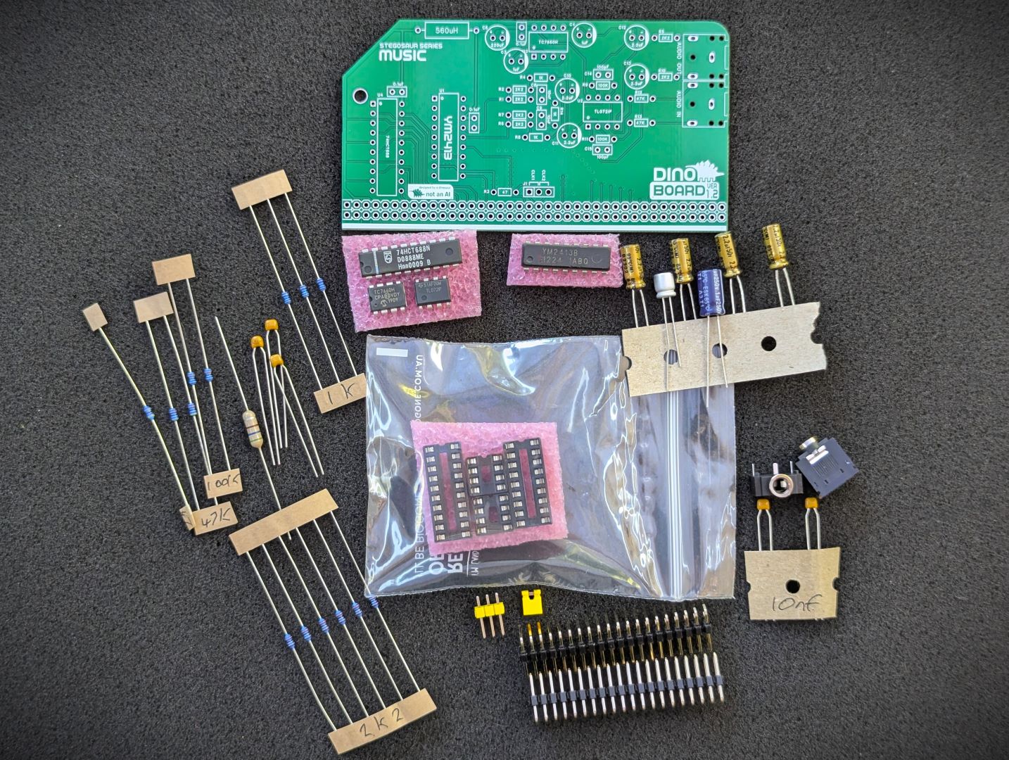 Base Kit Parts |
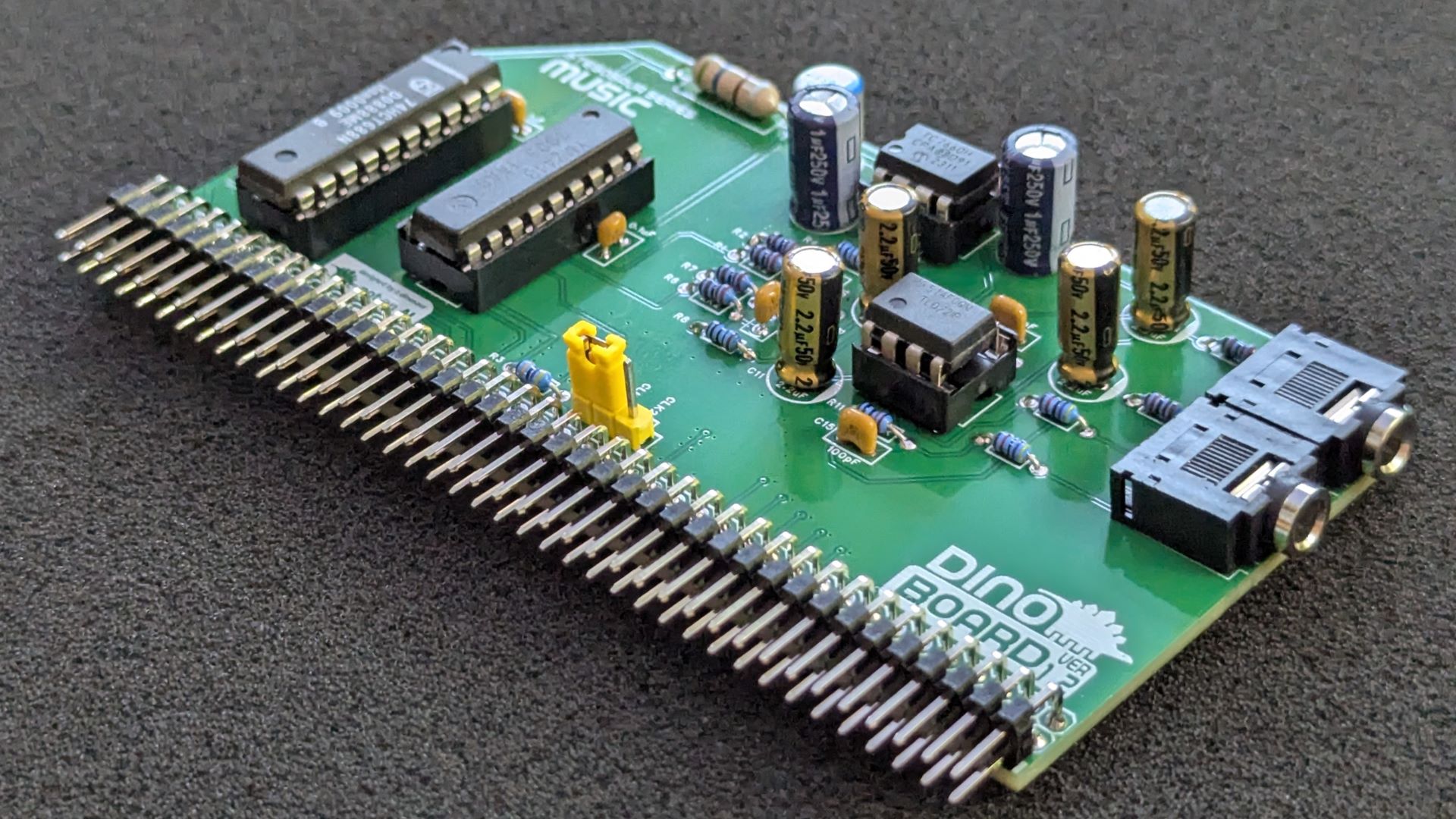
 Assembled Kit |
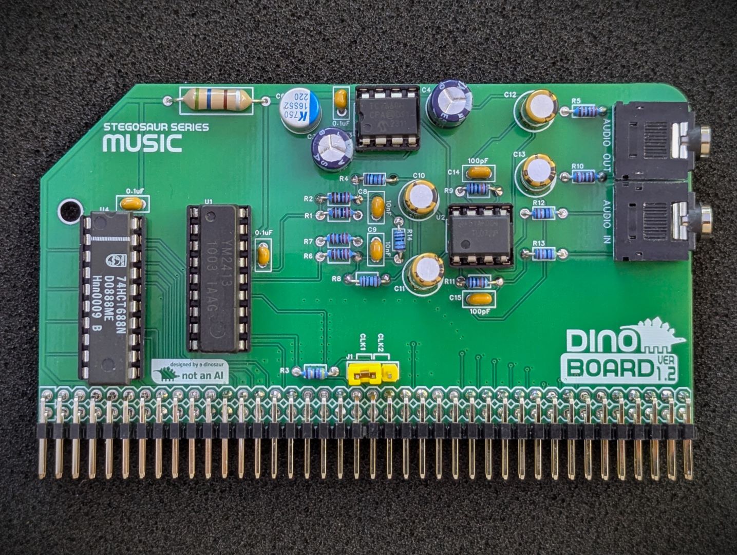
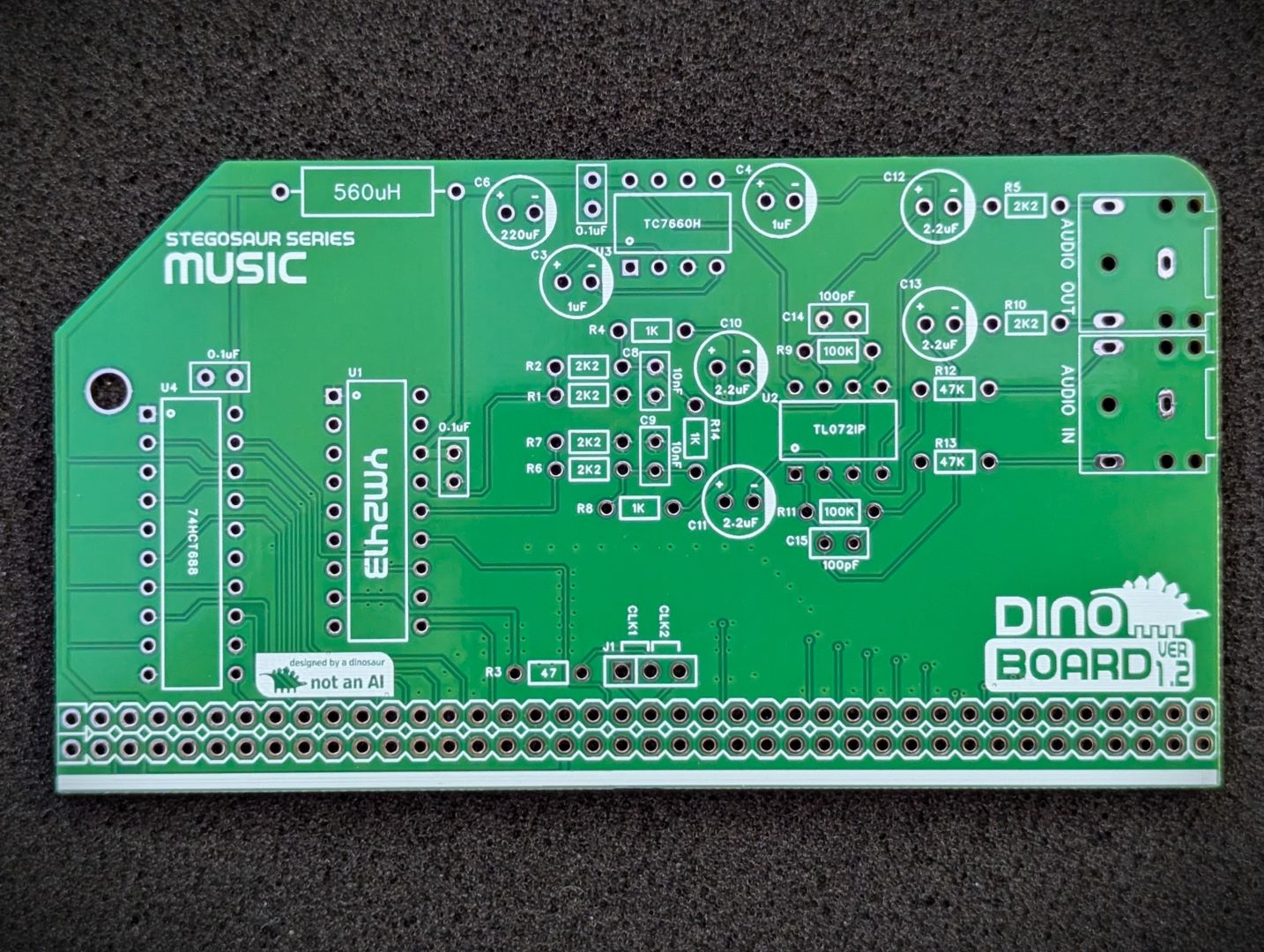 PCB Front |
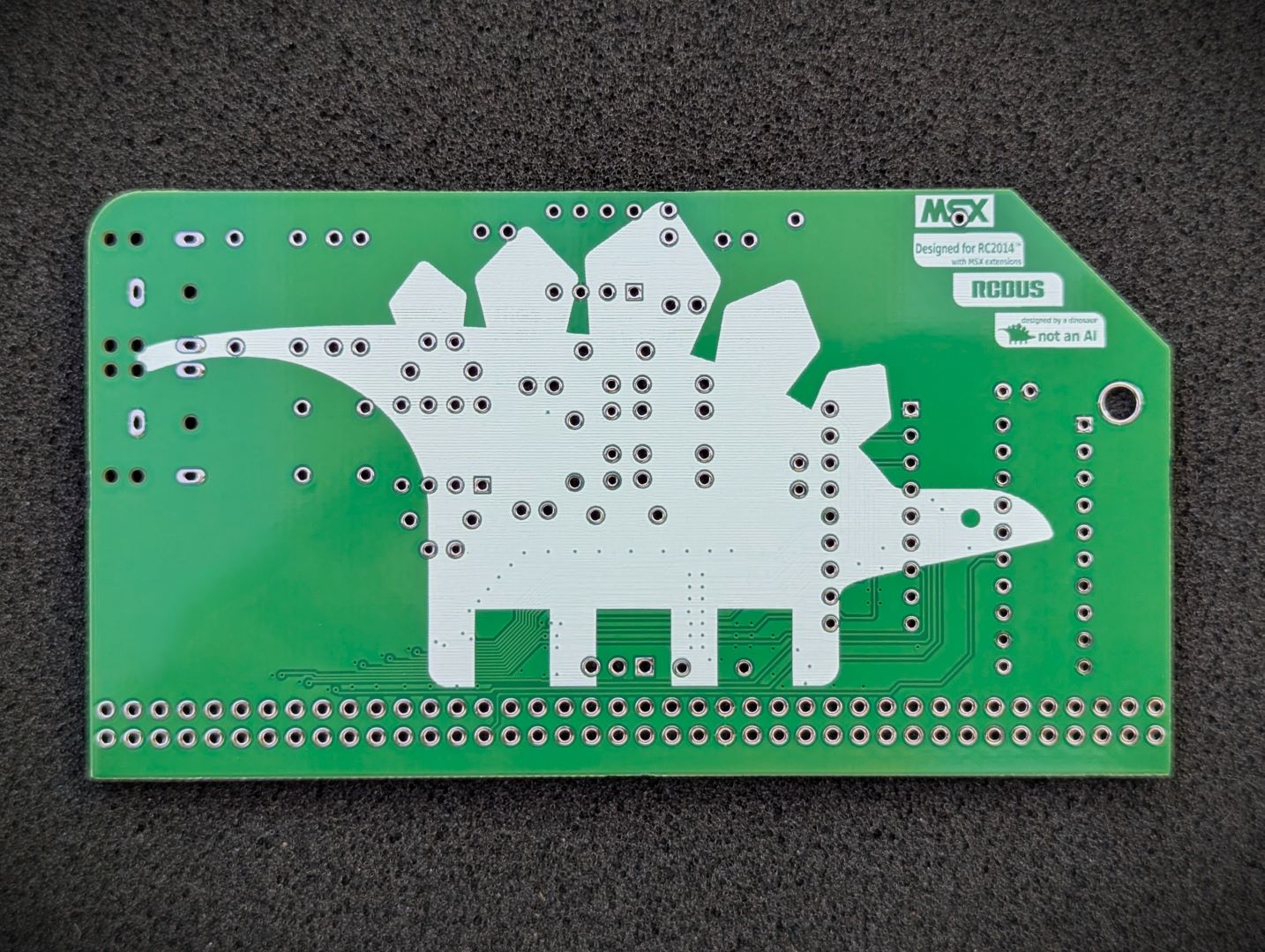 PCB Back |
* Self Source Reference are supplied as a guide only. Please double check, in case of typo or errors in listing.
| Count | Name | Self Sourcing* |
|---|---|---|
| 3 | 0.1uF Ceramic Capacitors | Mouser: 594-K104K10X7RF53L2 DigiKey: BC5137-ND |
| 2 | 3.5mm audio socket | Mouser: 490-SJ1-3523N DigiKey: CP1-3523N-ND |
| 2 | 1uF Electrolytic Capacitors | |
| 4 | 2.2uF Electrolytic Capacitors | |
| 1 | 220uF Electrolytic Capacitors LOW ESR | Mouser: 80-A750BG227M0JAAE20 DigiKey: 399-13660-ND |
| 1 | 560 uH Inductor | Mouser: 652-5300-34-RC |
| 1 | 47 Ω Resistor (3.4mm) | |
| 1 | 1K Ω Resistor (3.4mm) | |
| 1 | 2.2K Ω Resistor (3.4mm) | |
| 1 | 47K Ω Resistor (3.4mm) | |
| 1 | 100K Ω Resistor (3.4mm) | |
| 1 | TL072IP dual op-amp | Mouser: 595-TL072IP DigiKey: 96-14997-5-ND |
| 1 | TC7660 charge pump | Mouser: 579-TC7660HCPA DigiKey: TC7660HCPA-ND |
| 2 | 74HCT688 | |
| 1 | 20 POS IC SOCKET | Mouser: 571-1-2199298-6 DigiKey: 2057-ICS-320-T-ND |
| 1 | 18 POS IC SOCKET | Mouser: 571-1-2199298-5 DigiKey: 2057-ICS-318-T-ND |
| 2 | 8 POS IC SOCKET | Mouser: 649-DILB8P223TLF DigiKey: AE9986-ND |
| 2 | Right Angle 2x20 Header | Mouser: 649-68020-140HLF DigiKey: 2057-PH2RA-40-UA-ND |
| Count | Name | Self Sourcing* |
|---|---|---|
| 1 | Yamaha YM2413 |
| Count | Name | Self Sourcing* |
|---|---|---|
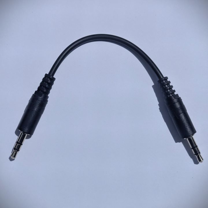
| 1 | Short 3.5mm audio cable |
This base kit includes the usual main components (PCB, capacitors, IC sockets, connectors, and the ICs)
A tested YM2413 can be optionally included or you can source your own.
The optional short 3.5mm audio cable is supplied to connect to the MSX Game Modules’s output and passthrough and mix with the Music module.
This module can work in a standard RC2014/RCBus RomWBW bootable system, or a MSX configured bootable system.
You need an external powered speaker to hear the audio. It is recommended to use stereo speakers to enjoy the stereo mix.
The connecting 3.5mm cable must be the 3 pole stereo type.
This module has 2 3.5mm stereo sockets. The top socket is the output to be connected to an external amplifier.
The lower socket is an input; typically connected to your MSX Game Module’s output, to pass through its audio signal.
Patch coming soon to the vgmplay.com application supplied with RomWBW.
This MSX-DOS application written by Laurens Holst, that will play VGM and VGZ music files. See the author’s site for more details: http://www.grauw.nl/projects/vgmplay-msx/
This application can be used in a CBIOS environment (with MSX-BASIC).
Select the bus clock lane to use for the module. CLK1 or CLK2. It expects a clock of approx ~3.5Mhz to ~3.6Mhz.
The board uses the standard IO addresses for MSX systems.
| Port | Description |
|---|---|
| $7C (w) | YM2413 register index |
| $7D (w) | YM2413 register data |
Please note that these IO port address conflict with the RC2014 512k ROM 512k RAM Module. As such to use RomWBW you need to use a ROM/RAM module that has tighter port selection. Recommend the SC714 RCBus Memory Module from Small Computer Central
| Description | Yellow MSX Version | Green Stegosaur Version |
|---|---|---|
| Audio Output | Mono signal via stereo 3.5mm connector | Melody (MO) and Rhythm (RO) outputs spread across the left and right channels |
| Passthrough input | mono only via 2 pin header | stereo mix via 3.5mm socket |
| Audio Quality | Lower top frequency | Brighter sound, with a higher top frequency roll-off and reduced digital noise |
| MSX Support | On board MSX-MUSIC ROM | Requires additional ROM Card for full MSX Support |
| Clock Source | On board clock | Requires external clock source, supplied via RC2014/RCBus’s CLK1 or CLK2 lane* |
| PCB Height | 8.0 cm | 5.5 cm |
| Colour | Yellow | Green |
* Unlike the Yellow MSX Music module, this module will not work unless you configure your system’s clock generator to produce an appropriate clock signal. The RC2014 Dual Clock Module, or similar can be configured to output a ~3.6Mhz clock onto the 2nd Clock lane. In MSX configuration it is expected that CLK1 will be set to the standard 3.6Mhz frequency.
Generally, you want to solder items from lowest height to largest height. Review the components you need to solder, and note their progressive heights.
* Note the right angle headers are position correctly and lay flush and at right angle to the main PCB.
Please note the following specific points regarding this module:
Please note that this is a kit, produced by a non-expert (me) for hackers, DIYers’ and retro lovers, to tinker with. Please exercise caution and follow good safety practices. You will be working with sharp knives, a hot soldering iron, and small metal components. Be mindful of the risks involved in the build process. I will do my best to answer any questions you may have.
This kit is provided as-is, with no guarantees or warranties. By assembling and using this kit, you acknowledge that you do so at your own risk.
 Store
Store