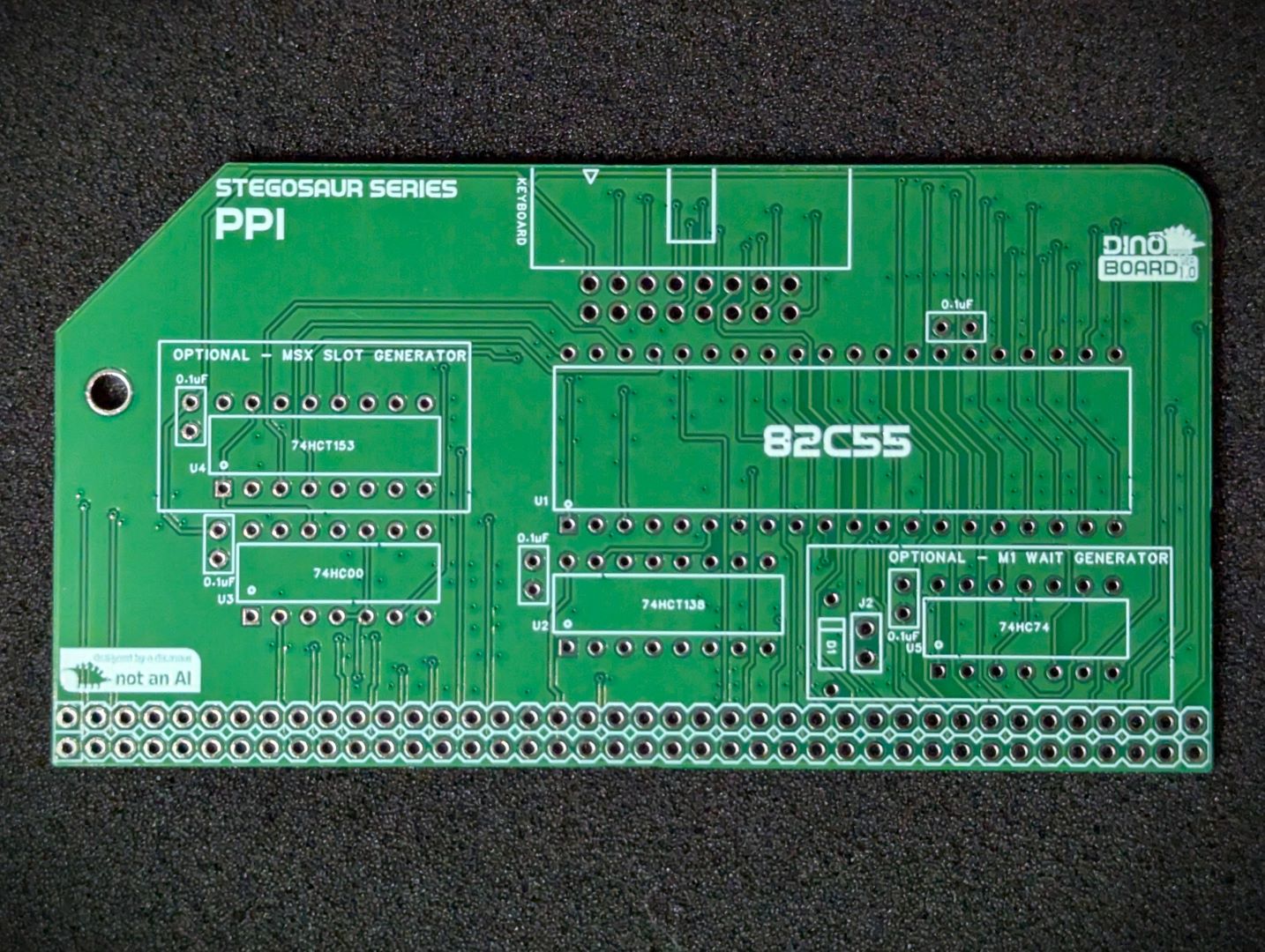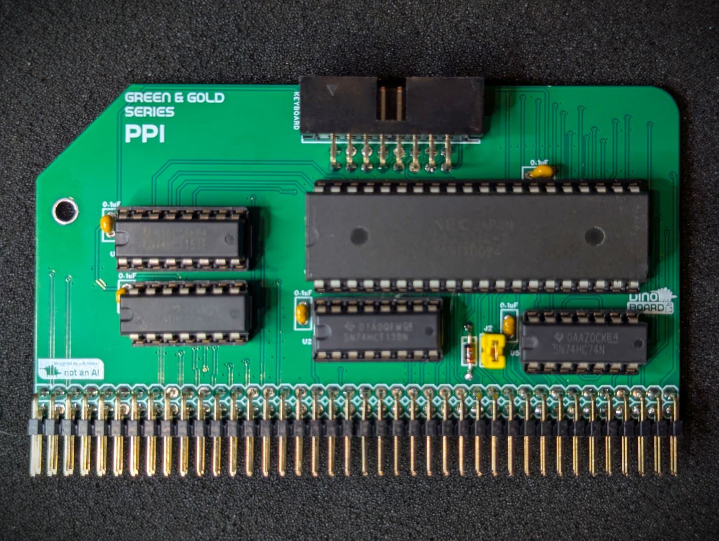
PPI Code: DB308
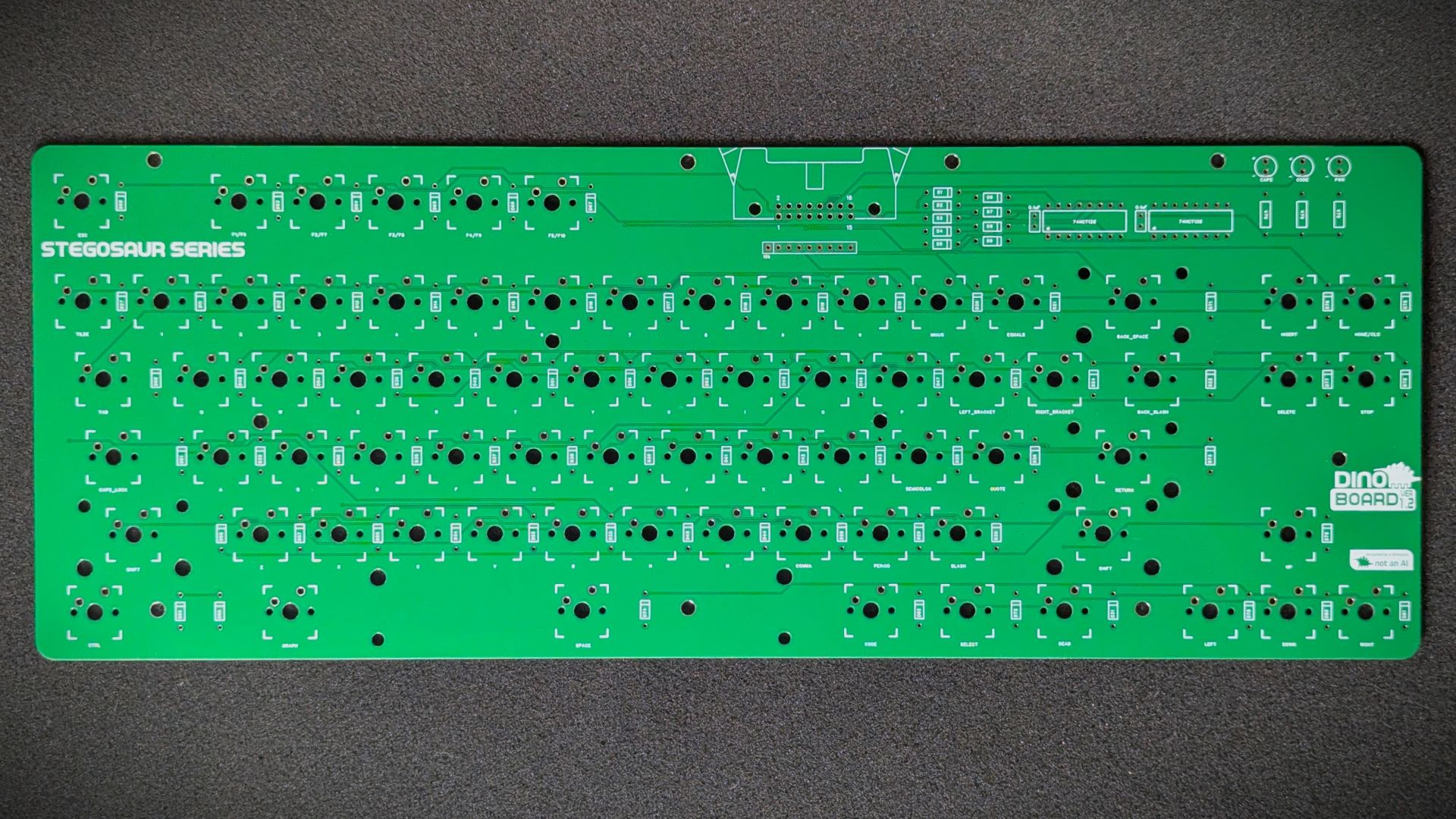
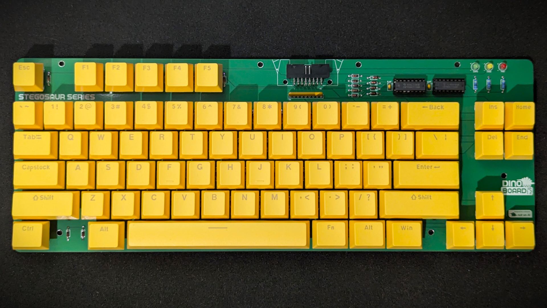
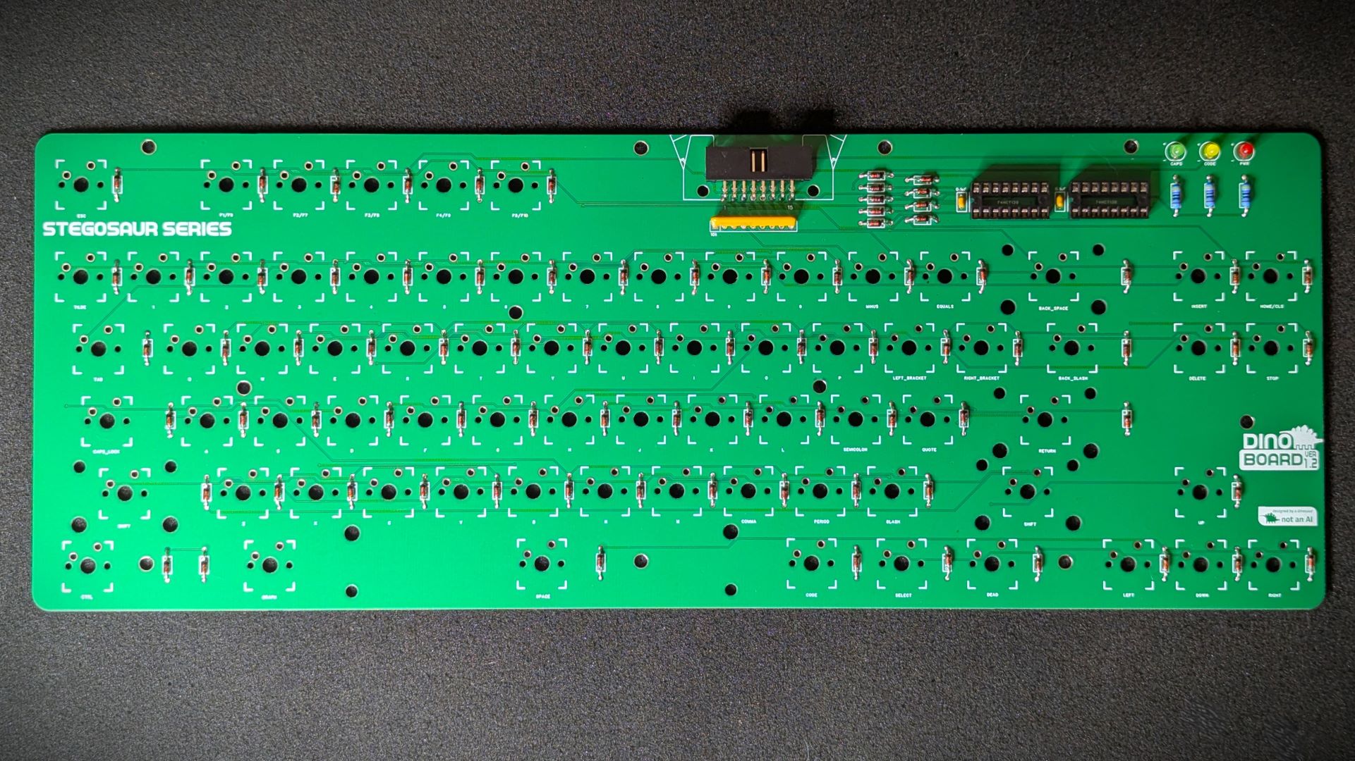
Keyboard: DB309
A full size keyboard kit for your RC2014/RCBus system giving your kit that perfect clicky keyboard.
* Self Source Reference are supplied as a guide only. Please double check, in case of typo or errors in listing.
| Count | Name | Self Sourcing* |
|---|---|---|
| 5 | 0.1uF Ceramic Capacitors | Mouser: 594-K104K10X7RF53L2 DigiKey: BC5137-ND |
| 2 | IDC Connector (No Clamps) | DigiKey: 2057-BHR-16-HUA-ND |
| 81 | 1N4148 | |
| 3 | 470 Ω | |
| 1 | 10k Ω Bussed (8) | Mouser: 652-4609X-1LF-10K DigiKey: 4609X-101-103LF-ND |
| 3 | 74HC138 | |
| 1 | 74HC00 | |
| 3 | 3mm LEDS | |
| 2 | Right Angle 2x20 Header | Mouser: 649-68020-140HLF DigiKey: 2057-PH2RA-40-UA-ND |
| 1 | 14 POS IC SOCKET | Mouser: 571-1-2199298-3 DigiKey: 2057-ICS-314-T-ND |
| 3 | 16 POS IC SOCKET | Mouser: 571-1-2199298-4 DigiKey: 2057-ICS-316-T-ND |
| 1 | 40 POS IC SOCKET | Mouser: 571-1-2199299-5 DigiKey: 2057-ICS-640-T-ND |
| 1 | 16 Way IDC Cable |
| Count | Name | Self Sourcing* |
|---|---|---|
| 1 | 0.1uF Ceramic Capacitors | Mouser: 594-K104K10X7RF53L2 DigiKey: BC5137-ND |
| 1 | 74HC153 | |
| 1 | 16 POS IC SOCKET | Mouser: 571-1-2199298-4 DigiKey: 2057-ICS-316-T-ND |
| Count | Name | Self Sourcing* |
|---|---|---|
| 1 | 0.1uF Ceramic Capacitors | Mouser: 594-K104K10X7RF53L2 DigiKey: BC5137-ND |
| 1 | 1N4148 | |
| 1 | 74HC74 | |
| 1 | 1x2 HEADER | |
| 1 | Shunt 1x2 | |
| 1 | 14 POS IC SOCKET | Mouser: 571-1-2199298-3 DigiKey: 2057-ICS-314-T-ND |
| Count | Name | Self Sourcing* |
|---|---|---|
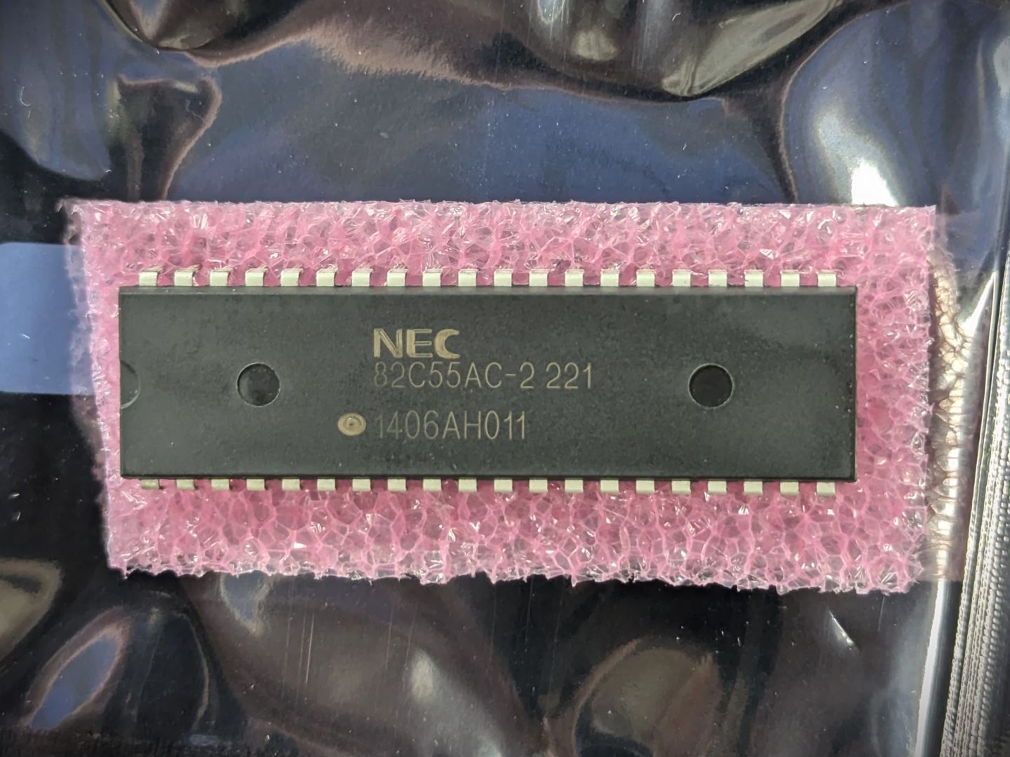
| 1 | 82C55 |
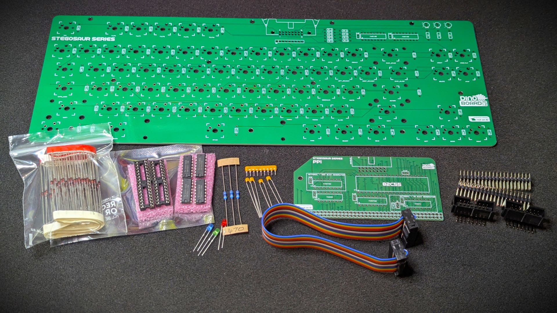
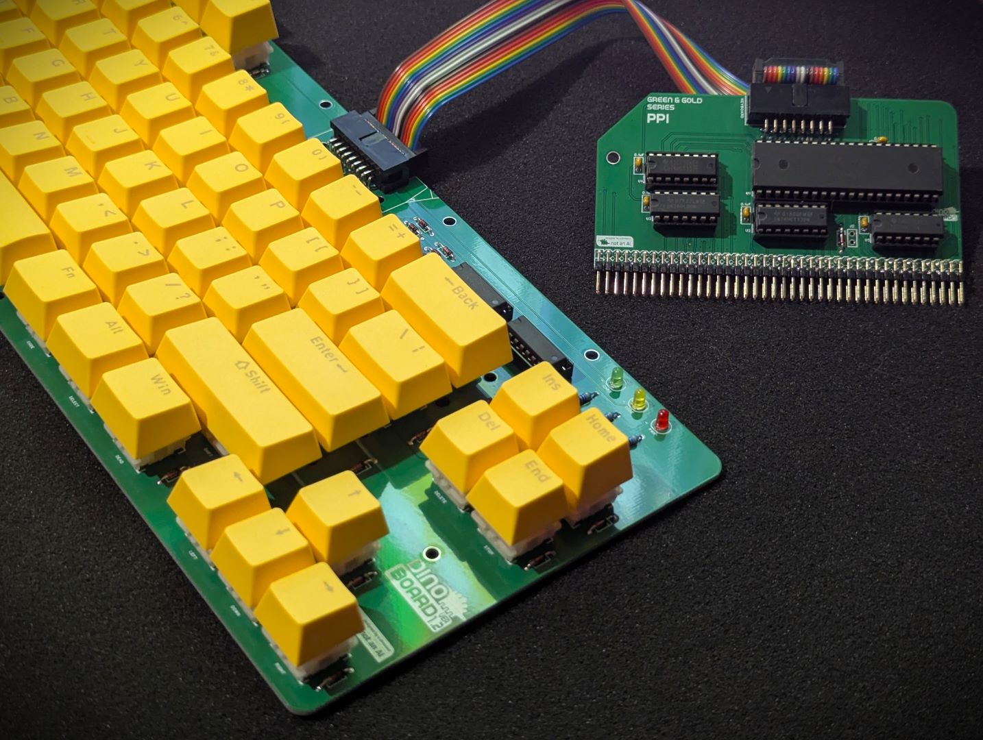
This project includes both the keyboard kit and the PPI interface board kit.
Please note, this kit does not include switches and keycaps. You can choose to source these yourself, or purchase the Keyboard caps here and compatible switches here
This module can work in a standard RC2014/RCBus RomWBW bootable system.
It is required for a MSX configured system.
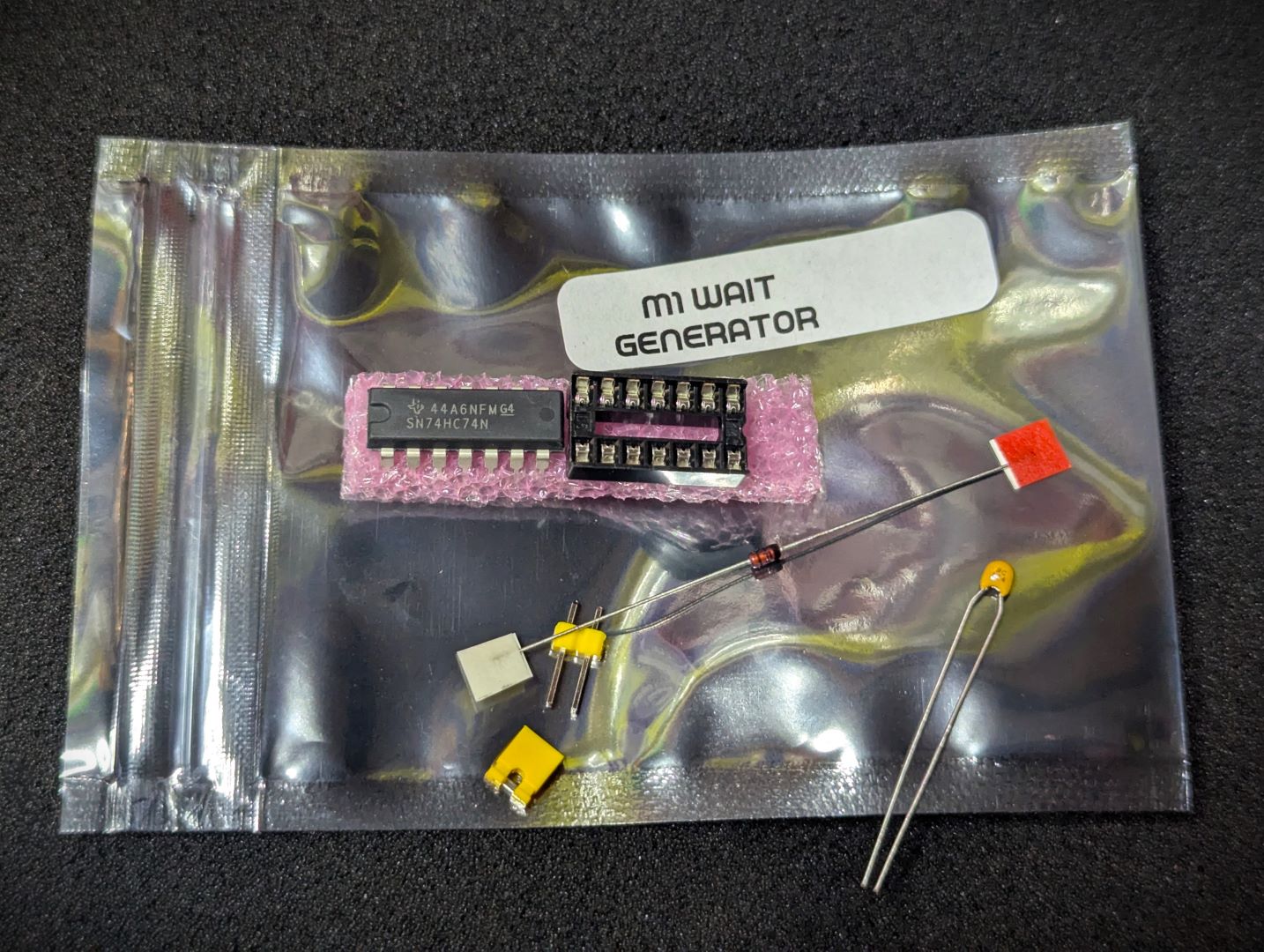
When shorted, a WAIT signal for 1 clock cycle is generated when the Z80 fetches a instruction. This is only required for MSX software compatibility. Short for MSX compatibility, leave unconnected otherwise.
When in MSX configuration or paired with the Turbo CPU, this jumper should not be shorted.
The MSX Turbo CPU modules also include a M1 Wait State Generator. Having the wait state generator of the PPI active, will cause the Turbo CPU to have additional unnecessary wait states.
Although this kit is designed to work under MSX’s software, it can be used in a stock RC2014 system with a correctly configured RomWBW ROM image.
See RomWBW for details on configuring and building a version of RomWBW for keyboard function.
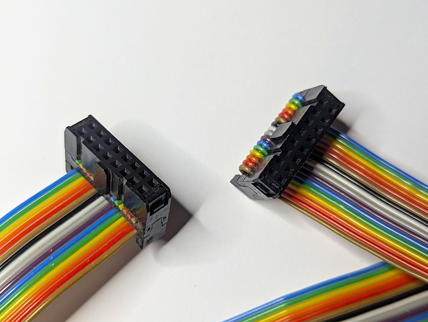
Its important that the correct rainbow 16 IDC cable is used. It needs to be a ‘straight thru’ type - as per image below.
| Description | Yellow MSX Version | Green Stegosaur Version |
|---|---|---|
| PPI PCB Height | 8.0 cm | 5.5 cm |
| IDC Connector | with locking clamps | without locking clamps |
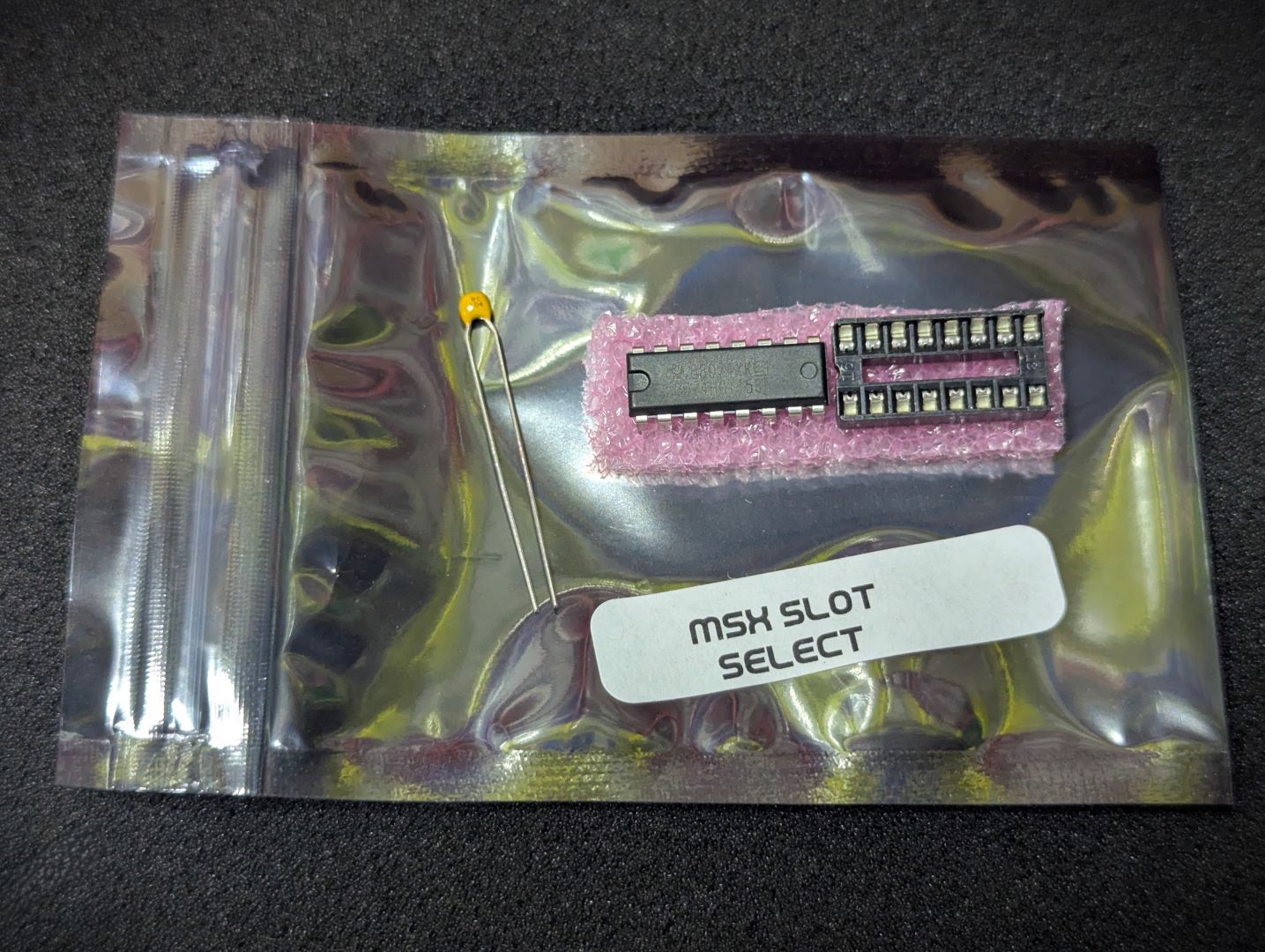
| Slot Selector | Included | Sold separately |
| M1 Wait Generator | Included | Sold separately |
| 82C55 PPI Chiip | Included | Sold separately |
| Backplane Requirement | 80 Way RCBus or RC2014 via external Jumpers | Wired permanently to 80 Way RCBus ‘User’ lanes (37-40, 77-80) |
| Colour | Yellow | Green |
Generally, you want to solder items from lowest height to largest height. Review the components you need to solder, and note their progressive heights.
* Note the right angle headers are position correctly and lay flush and at right angle to the main PCB.
Please note the following specific points regarding this module:
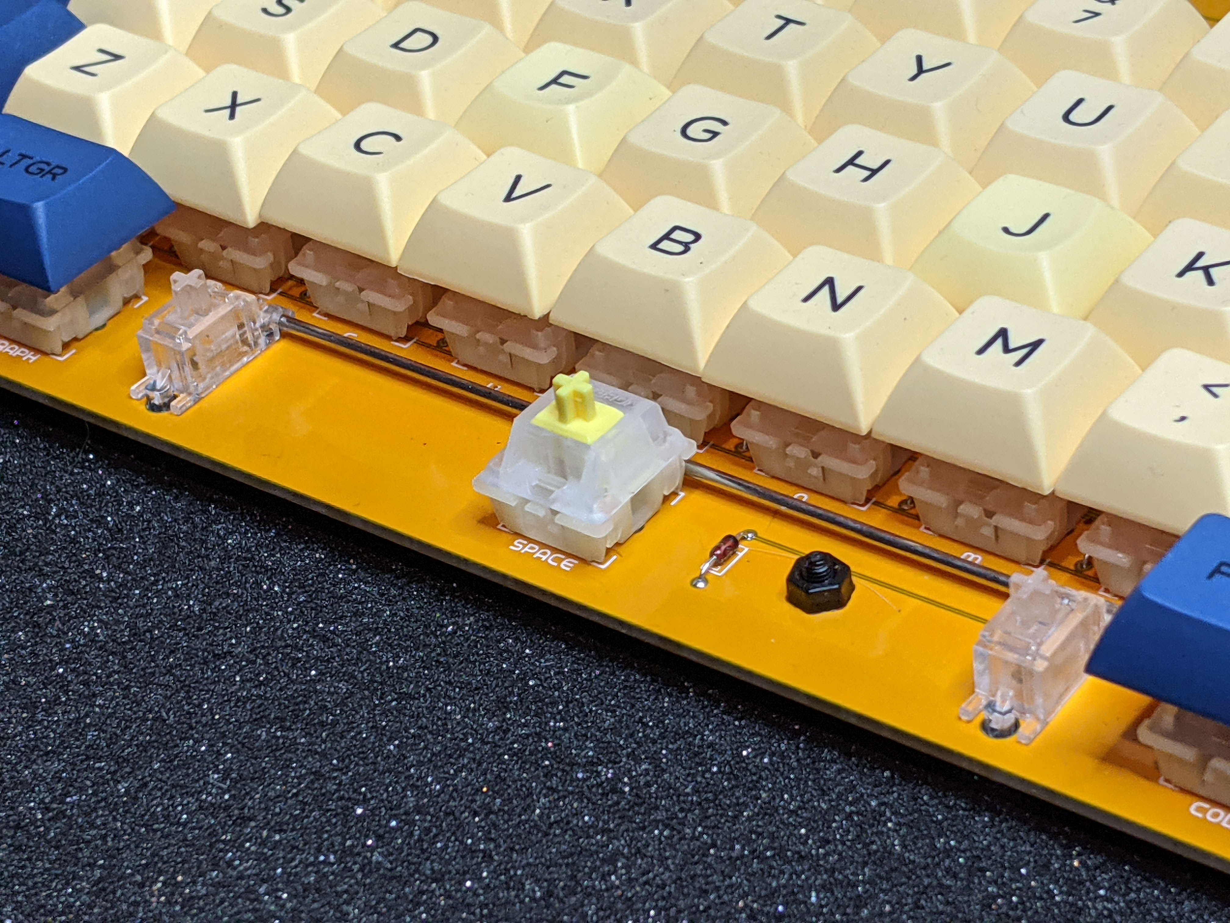
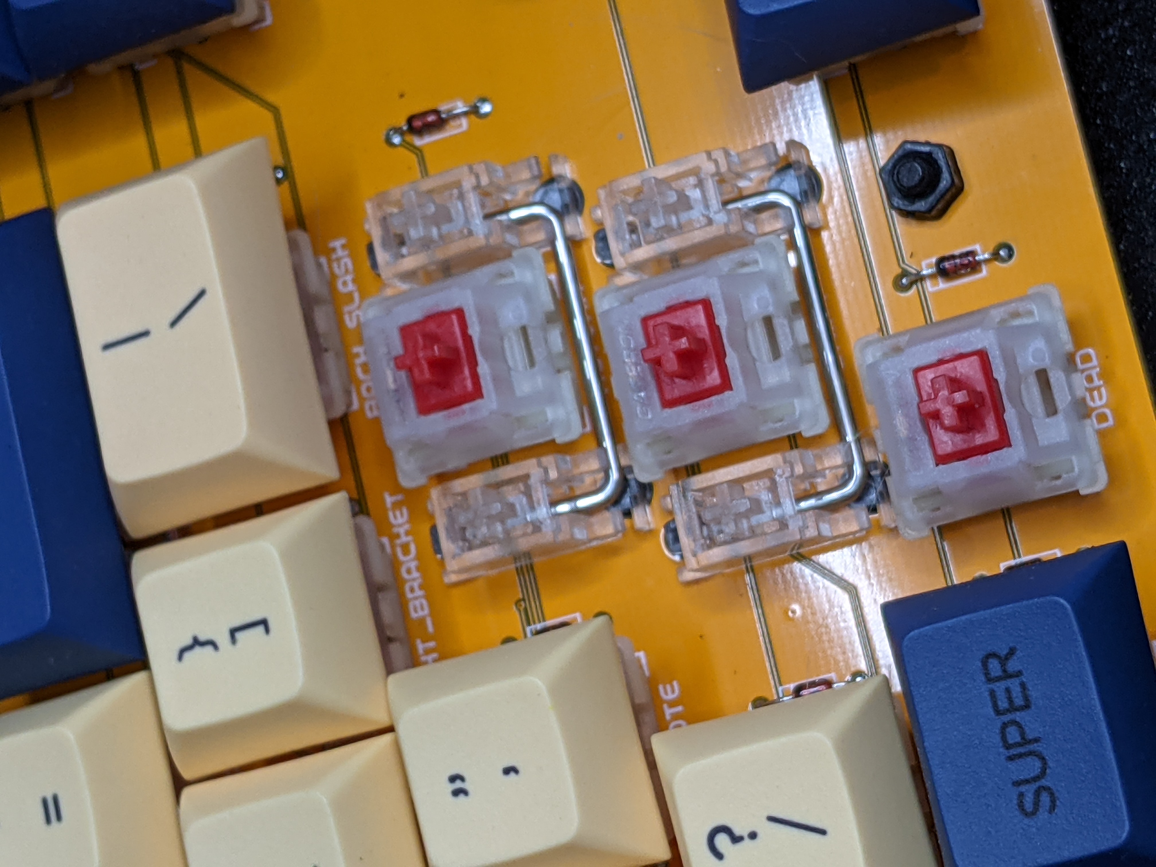
You will certainly want to solder the diodes on the keyboard before doing the switches.
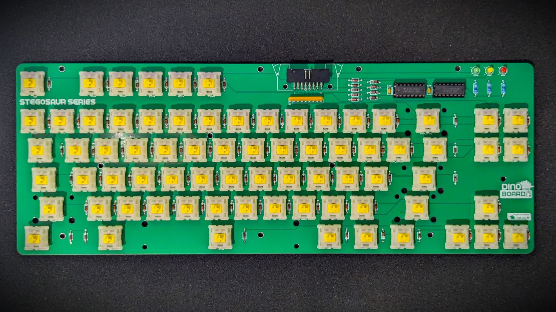
Mount the switches last – you should get a satisfying click as you push the switch into the board - but be careful that both pins have come thru cleanly. The pins are fairly thin and easy for them not to align and to be bent.
Start with just one or two switches first – push in, then check pins, then solder. Move onto a next set of switches. Once you are more comfortable, go for bigger batches - just keep an eye on the pins.
 |
 |
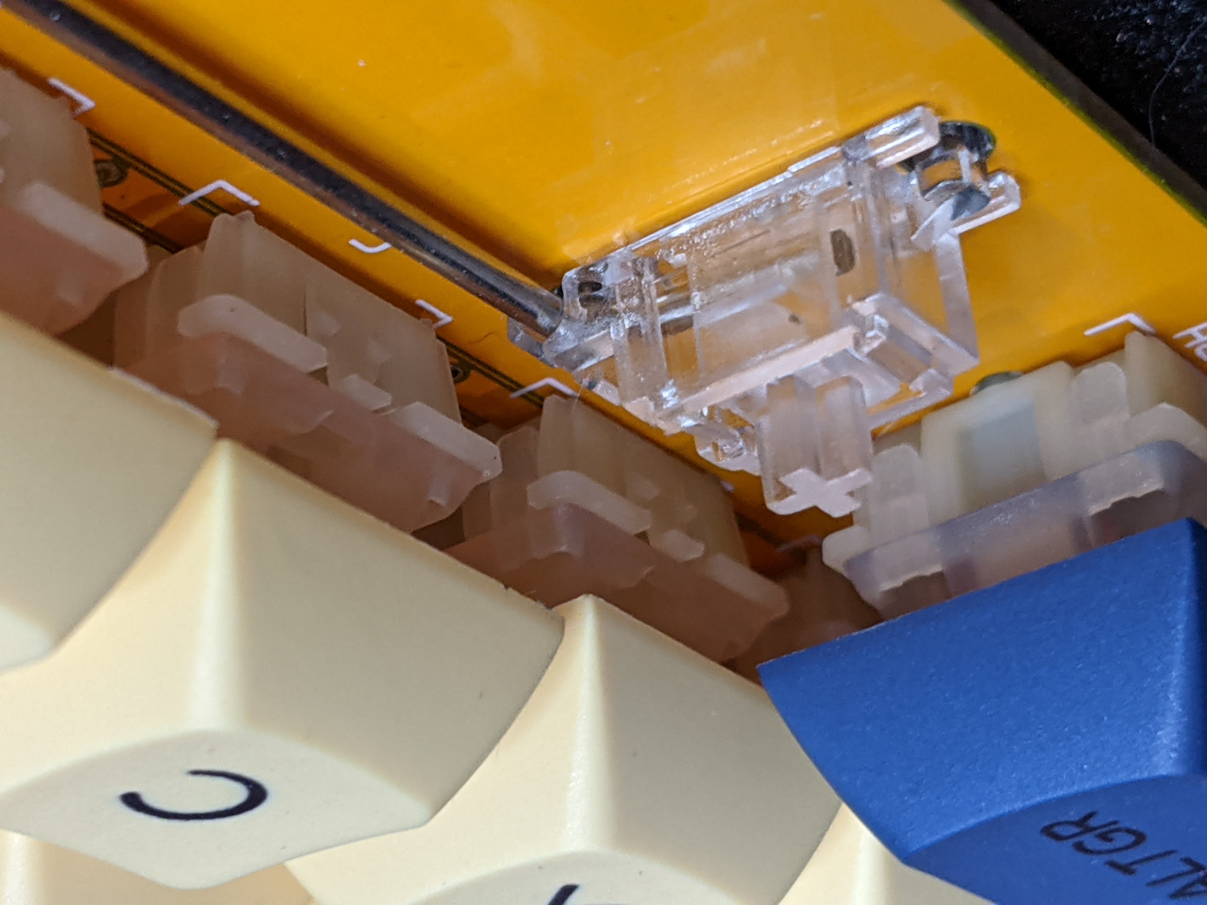
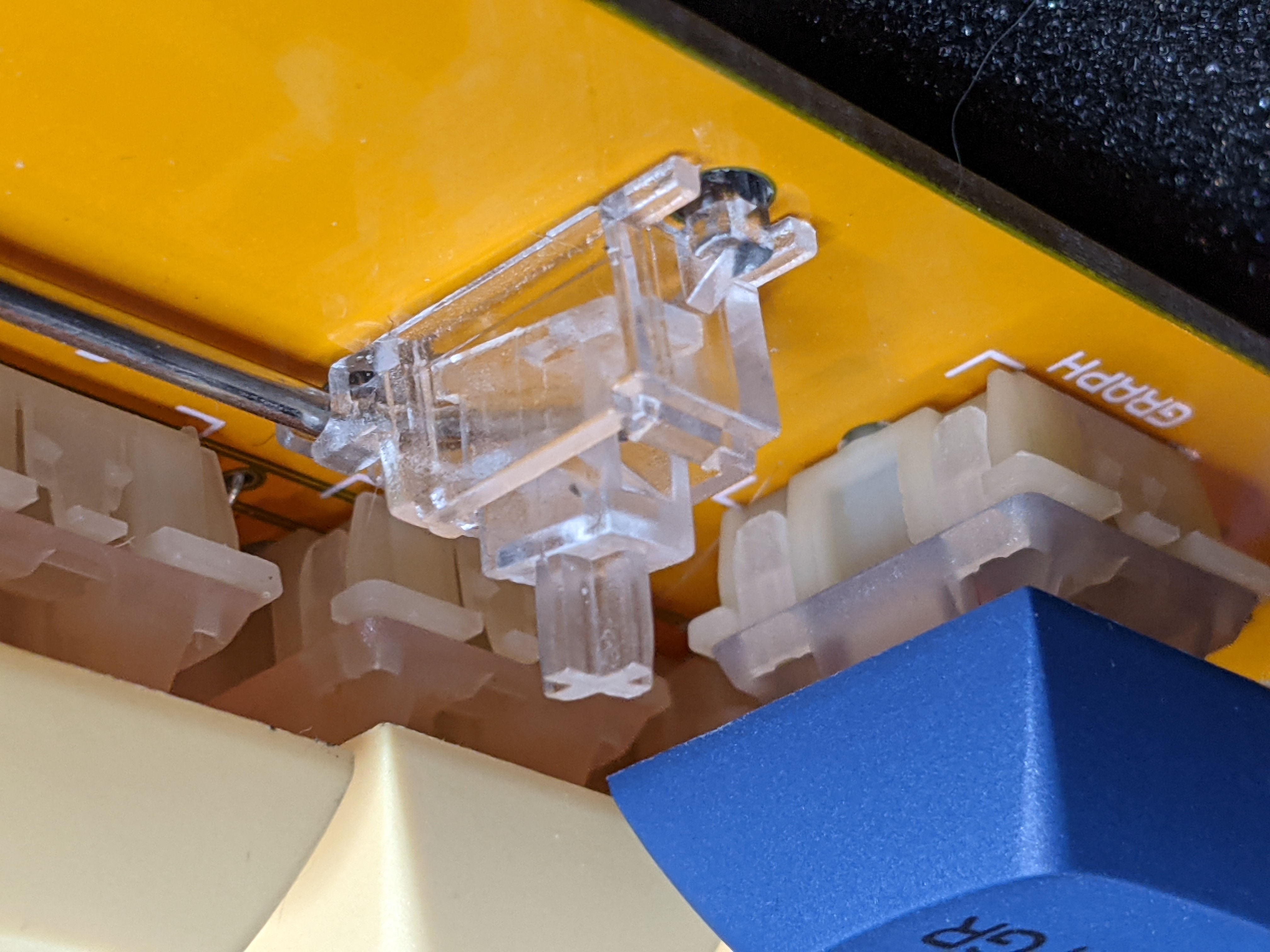
Once all the soldering is done, you can move onto mounting the stabilizers.
To assemble the stabilizers, you can use the following images to get an idea of how they go together.
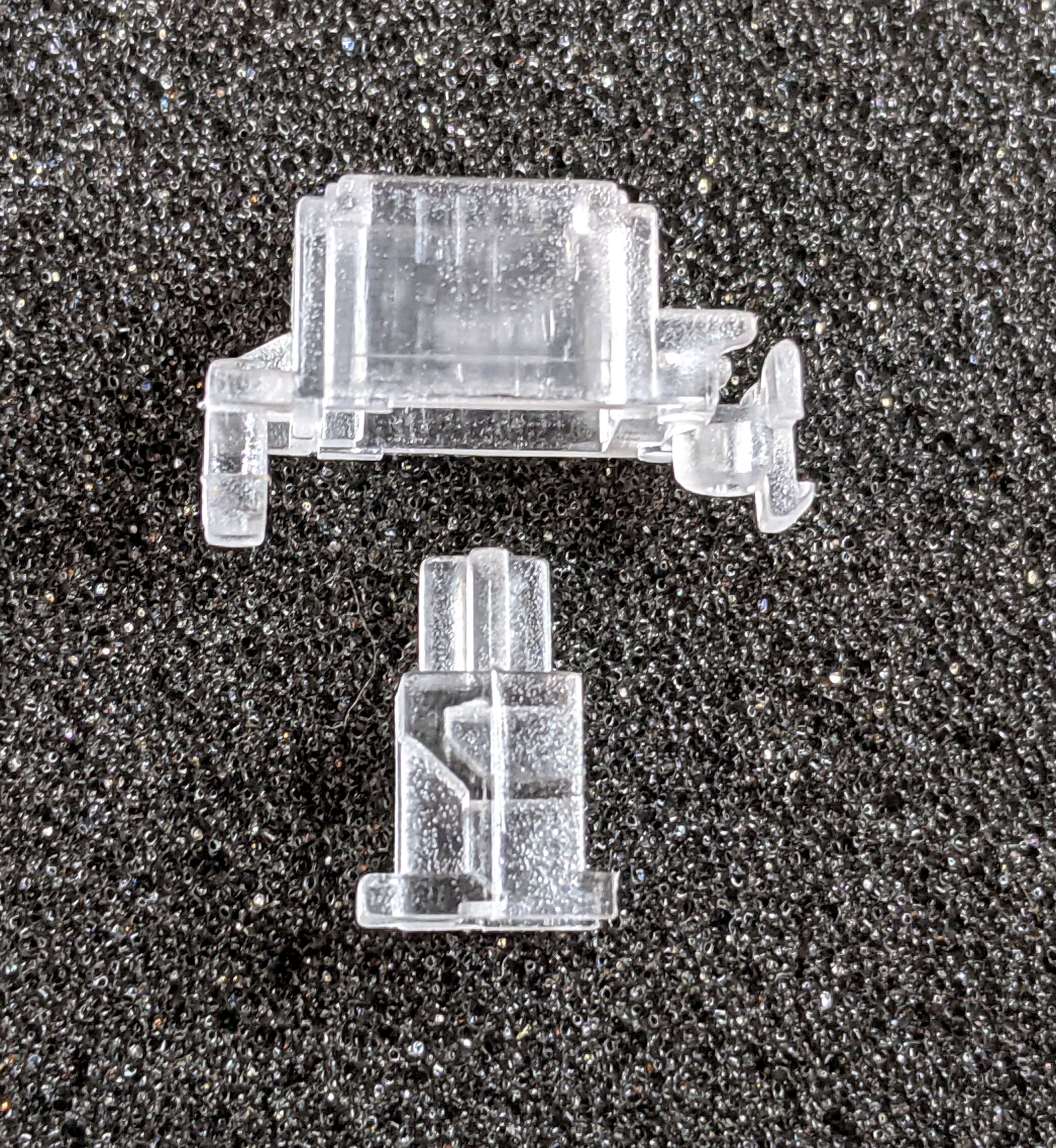
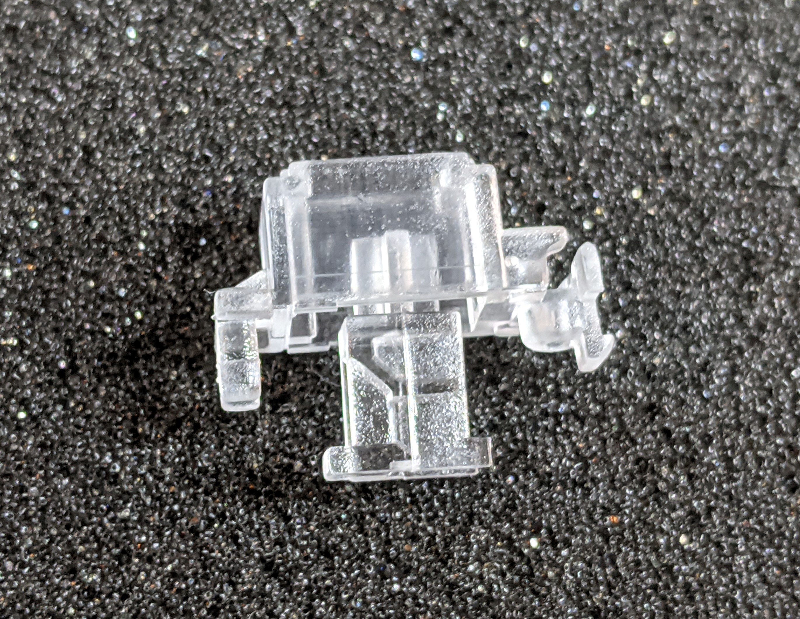
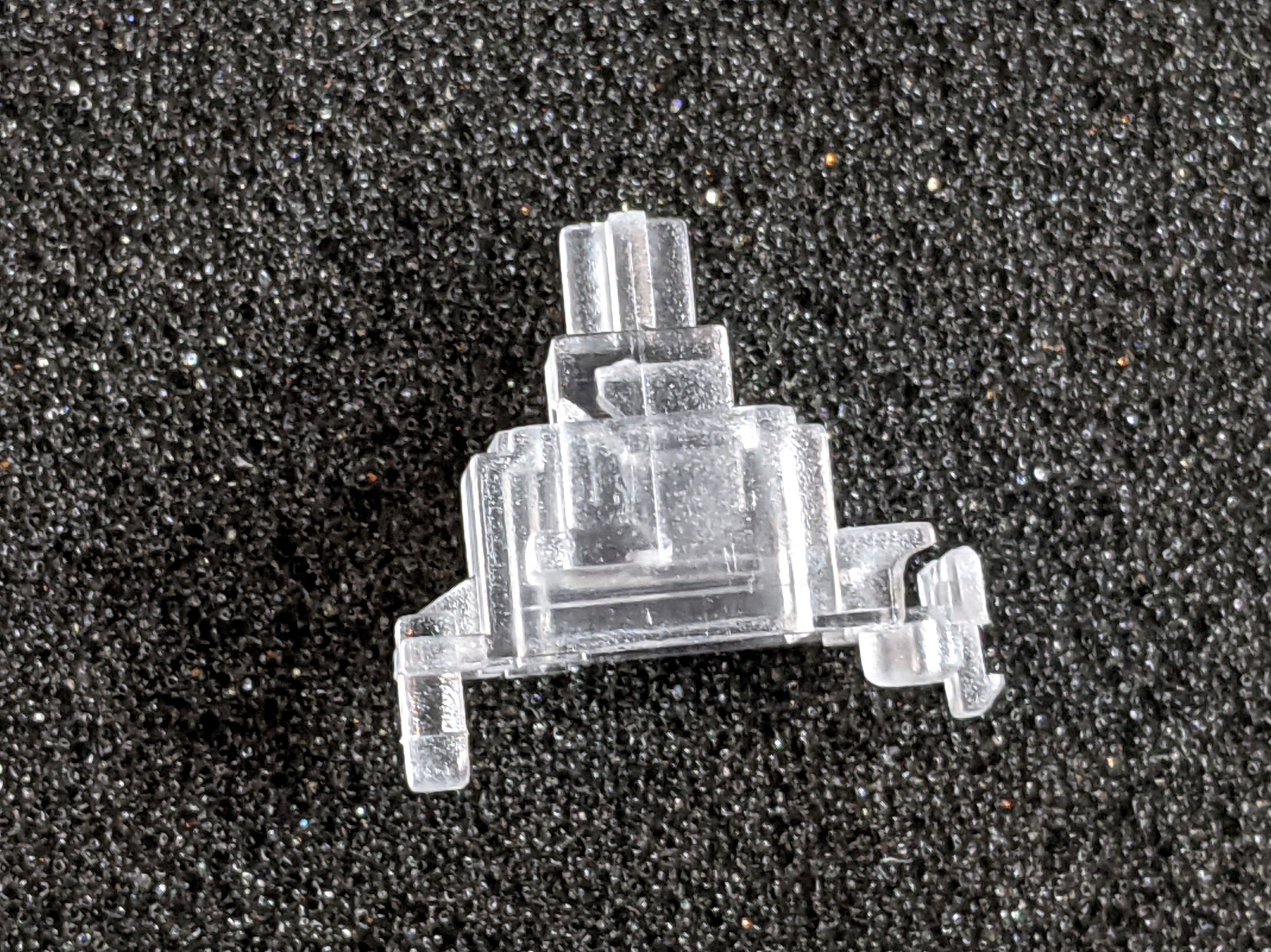
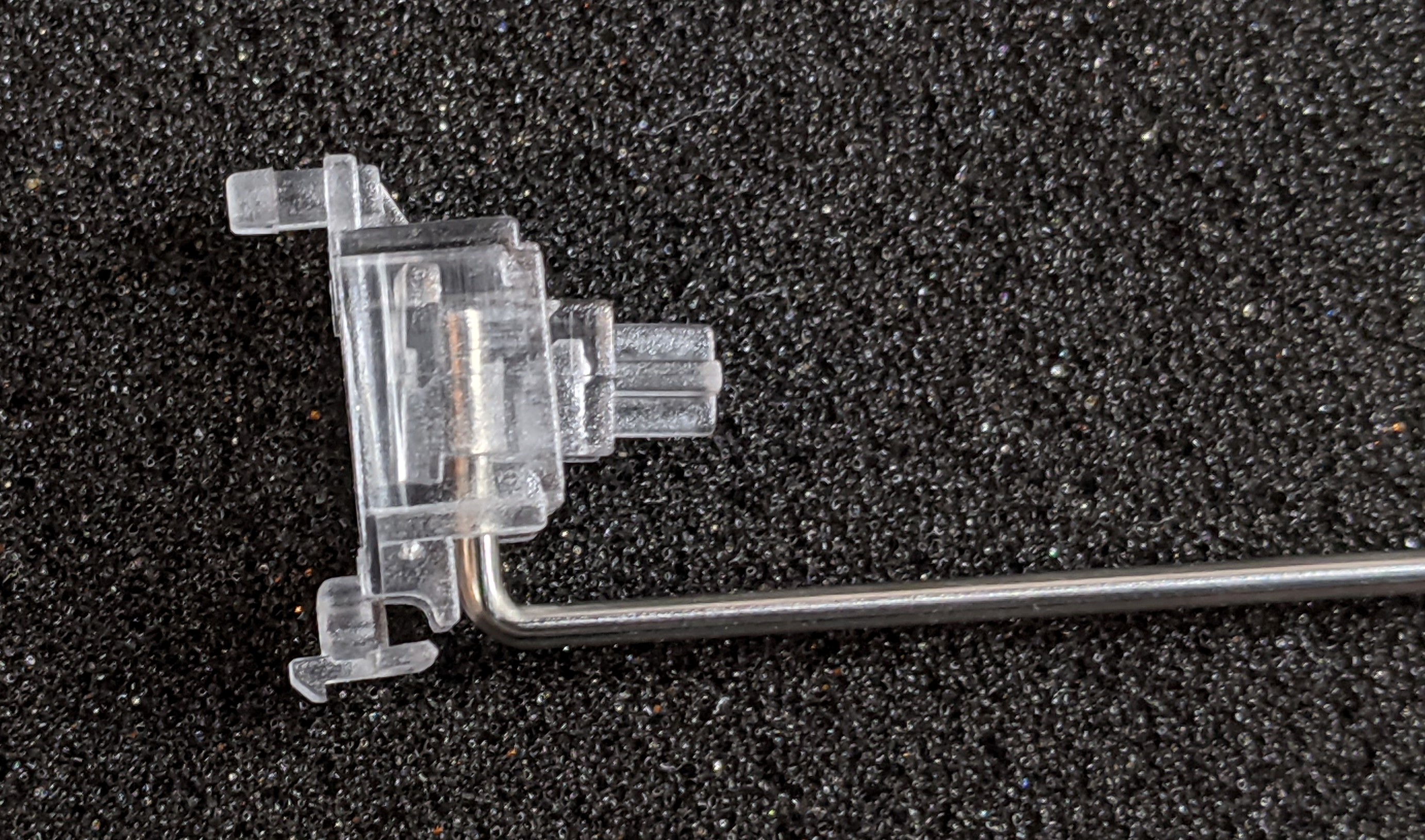
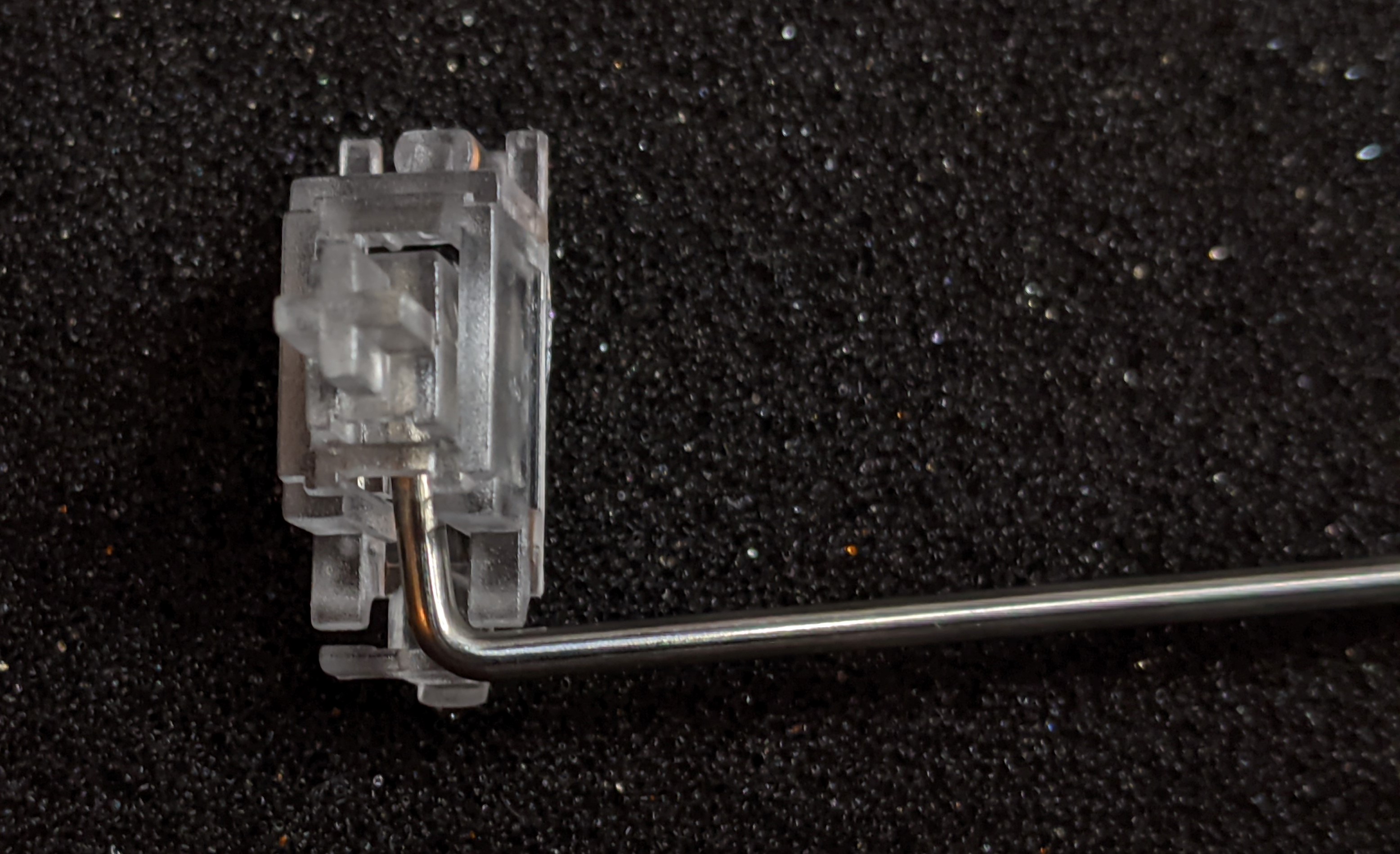
The insert should be able to move up and down as the bar is rotated.
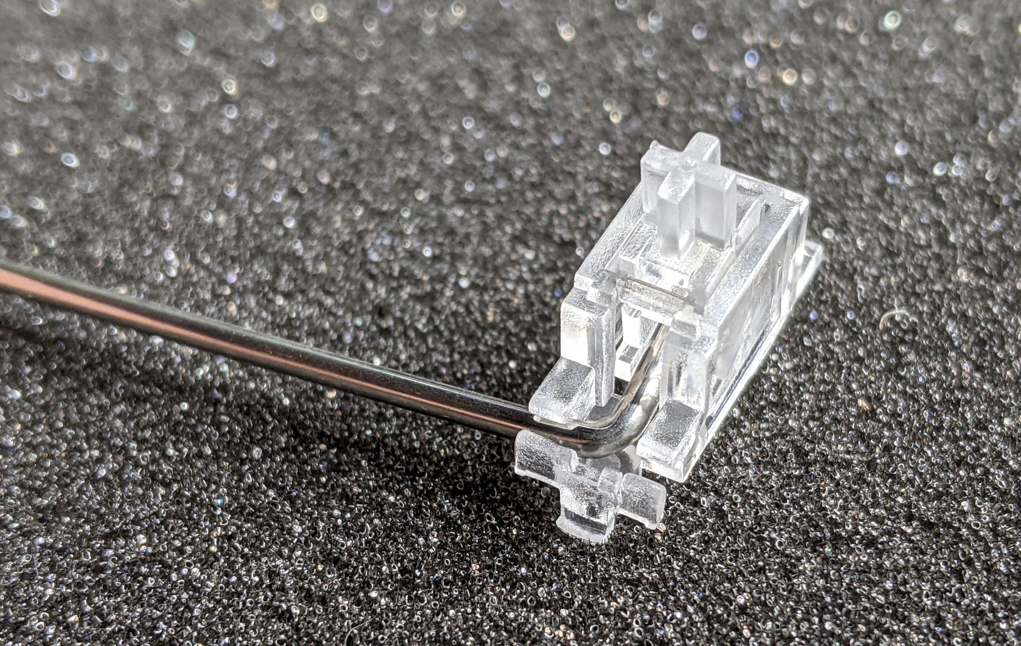
Repeat for the other side of the bar and for the rest of the stabilizers.
Once the stabilizers are assembled, you can now mount them on the PCB as shown below. The insert should be able to be moved up and down freely.
Please note that this is a kit, produced by a non-expert (me) for hackers, DIYers’ and retro lovers, to tinker with. Please exercise caution and follow good safety practices. You will be working with sharp knives, a hot soldering iron, and small metal components. Be mindful of the risks involved in the build process. I will do my best to answer any questions you may have.
This kit is provided as-is, with no guarantees or warranties. By assembling and using this kit, you acknowledge that you do so at your own risk.
 Store
Store