
Code: DB303
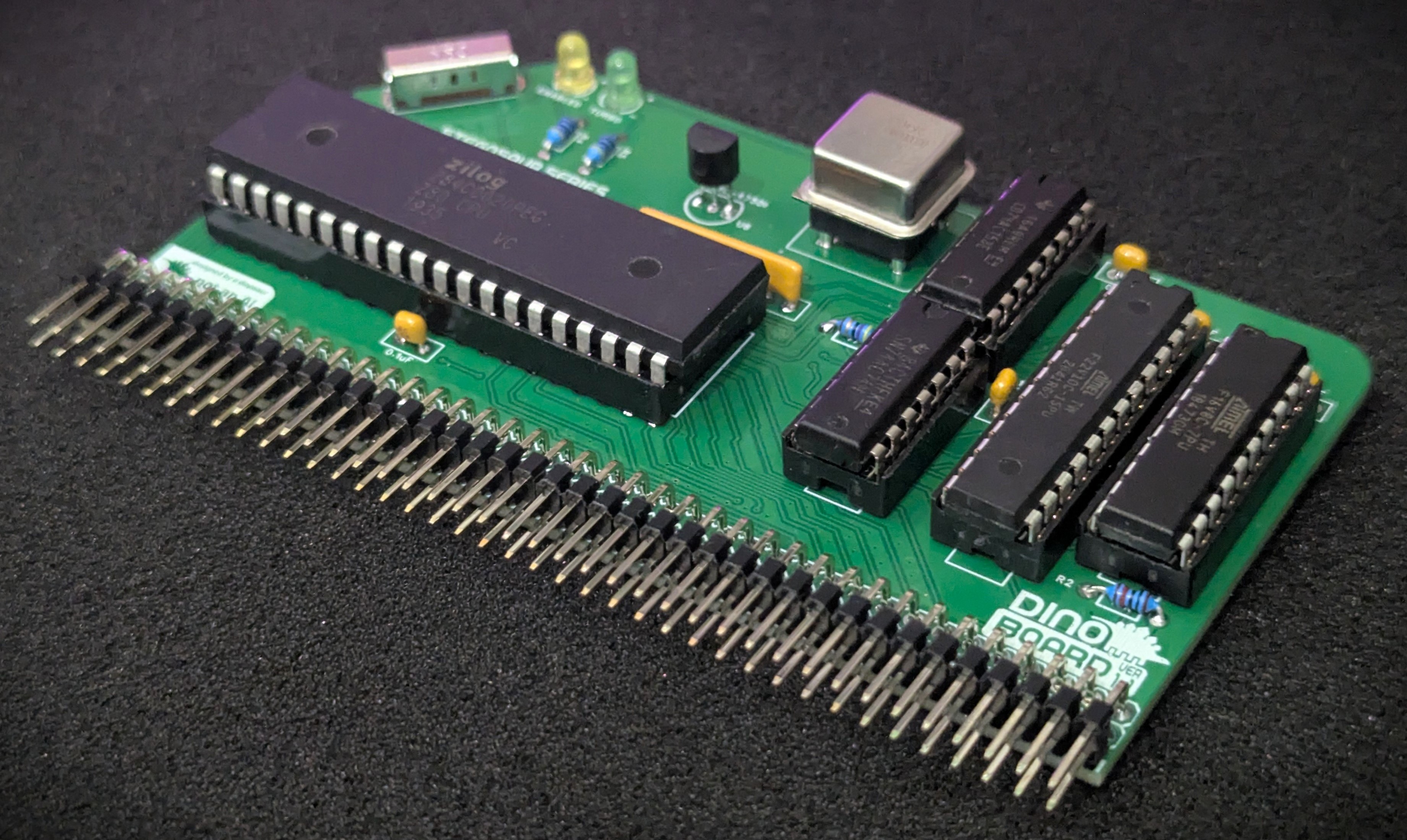
This module is designed to replace your existing RC2014/RCBus CPU and give you the full power of a Z80 running at 20Mhz, yet still be broadly compatible with original software and your other RC2014/RCBus modules.
For a system configured to run a full MSX configuration, you typically need to run your CPU at approximately 3.5Mhz, as software written for the platform at the time, would assume your system was clocked at this speed. If you attempt to run programs at a higher cpu clock speed, you will probably get video corruption, I/O problems – it just wont work!.
But these days, its possible to buy a brand new Zilog Z80 chip, rated at 20Mhz (Z84C0020PEG). For me in the mid 80s, that would have been an unimaginable speed!
We achieve compatibility by applying a combination of hardware wait states (pausing the CPU for a bit) and automatically slowing the clock down to the 3.5Mhz for short periods of time when the CPU is interacting with your other modules.
A 3 way slider, soldered on the front of the module, gives you total control of the CPU speed. Using this switch, you can at any time switch into 1 of 3 modes:
Despite the extra wait states and clock slow down, I have found a typical speed improvement of between 4 and 5 times faster - even for software the does lots of interactions with the V9958, you can still see a very large improvement.
Here is a demonstration of the very similar Yellow MSX Turbo CPU module, to give you an idea of the performance difference.
 |
 |
 |
 |
* Self Source Reference are supplied as a guide only. Please double check, in case of typo or errors in listing.
| Count | Name | Self Sourcing* |
|---|---|---|
| 5 | 0.1uF Ceramic Capacitors | Mouser: 594-K104K10X7RF53L2 DigiKey: BC5137-ND |
| 2 | 22pF | |
| 1 | 47 Ω (3.4mm) | |
| 2 | 470 Ω (3.4mm) | |
| 1 | 10K Ω (3.4mm) | |
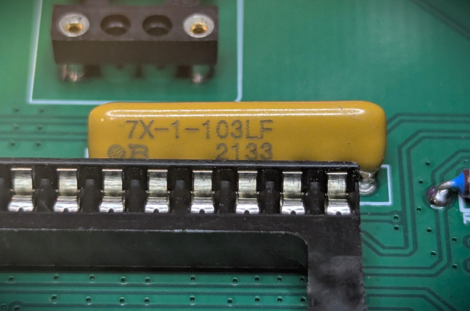
| 1 | 10k Ω Bussed x 6 | Mouser: 858-L071S103LF DigiKey: 4607X-101-103LF-ND |
| 2 | 3mm LED | |
| 1 | ATF22V10C | |
| 1 | ATF16V8 | |
| 1 | 74AC153 | |
| 1 | 74AC74 | |
| 1 | 74HC02 | |
| 1 | 74HC393 | |
| 1 | SP3T Slide Switch | Mouser: 611-OS103011MA7QP1 DigiKey: CKN9561-ND |
| 1 | 20 Mhz Oscillator | Mouser: 774-MXO45HS-3C-20.0 DigiKey: 535-9173-5-ND |
| 2 | Right Angle 2x20 Header | Mouser: 649-68020-140HLF DigiKey: 2057-PH2RA-40-UA-ND |
| 1 | 40 POS IC SOCKET | Mouser: 571-1-2199299-5 DigiKey: 2057-ICS-640-T-ND |
| 1 | 24 POS IC SOCKET NARROW | Mouser: 571-1-2199298-8 DigiKey: 2057-ICS-324-T-ND |
| 1 | 20 POS IC SOCKET | Mouser: 571-1-2199298-6 DigiKey: 2057-ICS-320-T-ND |
| 1 | 16 POS IC SOCKET | Mouser: 571-1-2199298-4 DigiKey: 2057-ICS-316-T-ND |
| 4 | 14 POS IC SOCKET | Mouser: 571-1-2199298-3 DigiKey: 2057-ICS-314-T-ND |
| 1 | 4 OSCILLATOR SOCKET | Mouser: 535-1108800 DigiKey: A463-ND |
| 1 | PCB |
| Count | Name | Self Sourcing* |
|---|---|---|
| 1 | Z80 20Mhz | Z84C0020PEG |
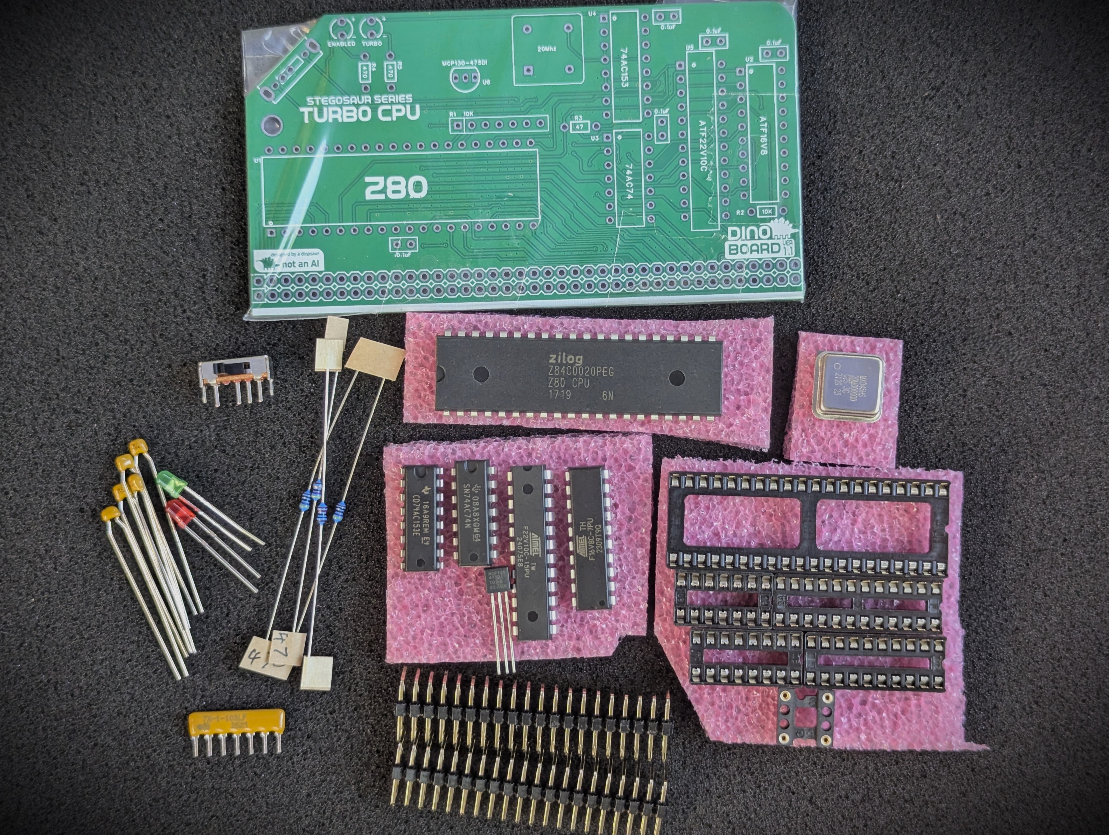
The full kits includes everything you need (PCB, capacitors, IC sockets, connectors, and the ICs).
The ATF22V10C and ATF16V8 PLD chips are supplied flashed.
The optional Z80Mhz can be included or you can source your own.,
This module is designed to drive a standard RC2014/RCBus RomWBW system, or a MSX configured system.
Unlike the Yellow Turbo CPU Module, this module still requires an external clock source (slow-clock). This slow clock can be generated using any RC2014/RCBus clock modules (eg: The RC2014 Dual Clock Module). You can also use the V99x8 RGB Video modules, with their appropriate jumper settings to create a ‘slow clock’ signal onto the CLK1 bus lane.
I have tested running at 20Mhz on my specific back-plane and set of modules without any problems. But due to differences in combination and configuration of RC2014 kits - you may find with your specific situation, there are signal degradation issues at 20Mhz that may cause non-reliable operation. You can use the 3 way slider to force the module to operator at a lower speed and ensure good compatibility
The 3 way slider at the front of the module is used to change the timing settings of the Z80. In its top most position, the CPU will operate at the speed as per your bus clock.
In the middle position, the processor will boost to 20Mhz, but it includes 3 WAIT states for all memory access.
In the bottom position, the processor will boost to 20Mhz, but only have 1 additional WAIT state added for any memory access.
Running RC2014 build at higher clock speeds presents a few challenges for reliable operation. To increase the CPU clock speed of your system, a few things need to be considered:
All the various I/O modules and RAM/ROM modules available for RC2014 typically expect an operation frequency of between 3.5Mhz and 7Mhz. So if we increase the clock frequency of the CPU, we have to figure out a way to ensure a wide range of compatibility with all these external modules.
One of the things that work in our favour though, is despite the fact the Z80 is running at 20Mhz, it will not access I/O and memory at this rate. This is due to the way it requires a few internal clock cycles for various operations, so the effective rate of communications to modules will be lower. For example, all I/O request take at least 4 Clock cycles to complete, and some instructions processed by the Z80 can take up to 20 clock cycles. We have to consider the timing requirements and operation of the Z80 as described in its datasheet.
The Z80 supports the concepts of additional hardware based wait states. By designing some logic to enable extra wait states when accessing I/O and memory devices, we can force the CPU to ‘wait’ or pause for additional clock cycles, thus allowing the I/O and memory chips the time they need to process the read/write requests from the CPU.
It also important to remember, that even at the 3.5Mhz clock speed, the original MSX standard required an extra wait state when reading memory during the M1 cycle. This was required as the speed of memory, particularly ROM chips of the day, were not able to keep pace with a Z80 running at 3.5Mhz. Although modern RAM and ROM chips are quite capable of keeping up, if we remove this wait time, original software and games may not work right.
The V9958 in particular, presents a compatibility challenge when running the Z80 at a higher clock speed. So much original software will be optimise to send commands to the V9958, on the assumption that the CPU is running at 3.5Mhz. Although, with my testing to date, I found the V9958 can communicate with a Z80 running at 7Mhz. This will only work as long as our software manages the rate at which it issues commands to the V9958. Original unaltered software, typically will cause video corruption, even at 7Mhz.
The timing requirements for the V9958 can be quite complicated. Depending on if you are issuing a command or attempting to access the VRAM the time that’s needed between 1 operation and the next can be quite confusing to figure out. Despite this, the software authors, have optimised this to the highest possible degree. For a detailed analysis of the timing, check this article out. Any increase in CPU speed without hardware waiting, will cause original software to not work. But if we go with ‘pausing’ the CPU to achieve compatibility, running at 20Mhz, we may need to pause the CPU for 90 clock cycles (or more).
So to solve this problem, instead of ‘pausing’ the CPU, I went for a different approach. When I/O interactions are undertaken by the Z80, the Z80’s clock is switched from the 20Mhz rate, down to the standard 3.5Mhz. The CPU is feed this slow clock for 31 clock cycles (at 3.5Mz), after which it revert the clock back to the full 20Mhz. I found that about 30 odd cycles was enough to achieve general compatibility.
The clock signal supplied to the CLK1 RC2014/RCBus bus is typically independent of the clock signal sent to the CPU. When the CPU is operating at the full 20Mhz, the CLK1 signal, will continue at its selected rate. So other modules that use this clock signal, such at the SIO/2, and will not see any difference in clock signals.
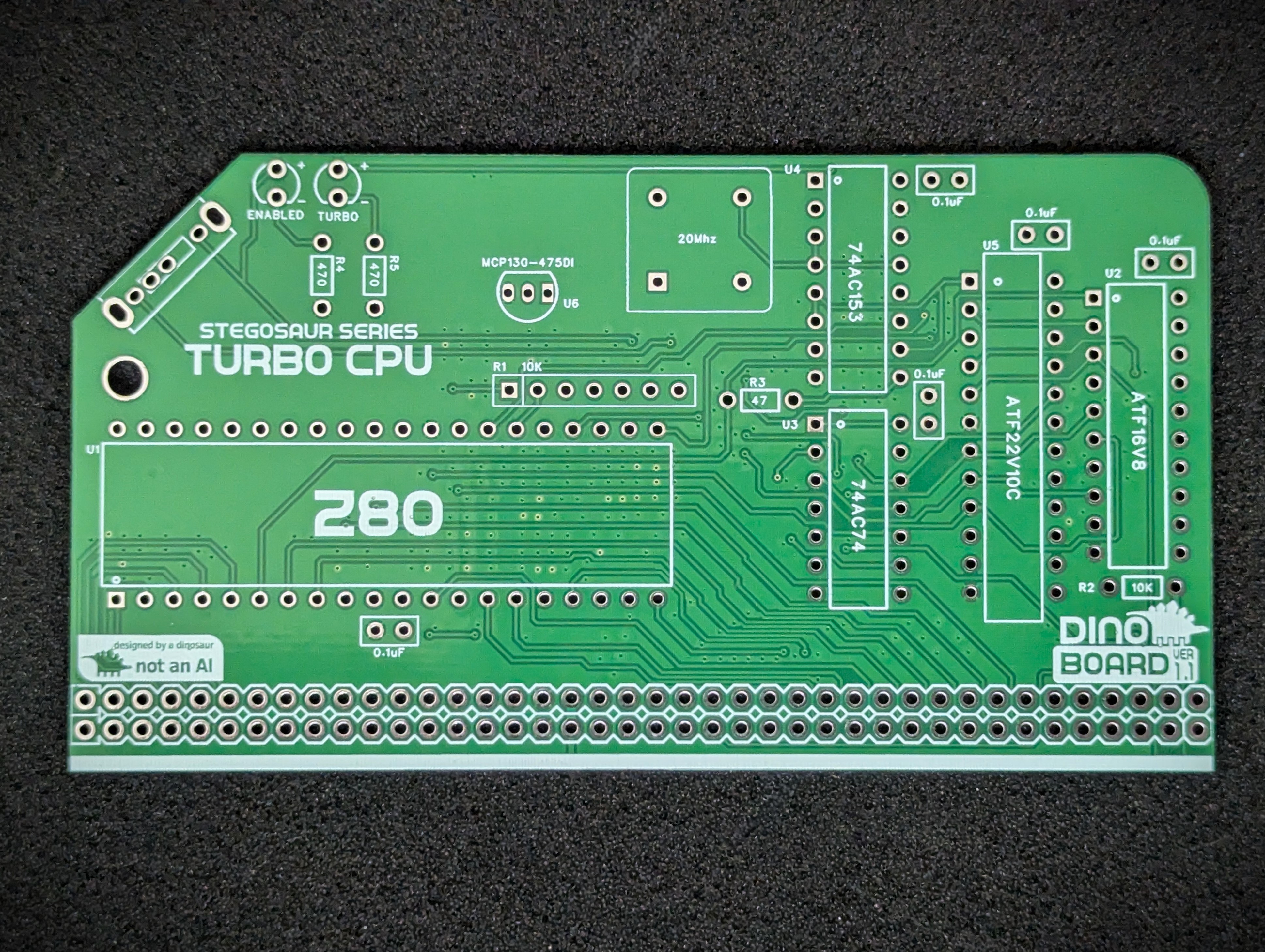
This module has 2 (Programable Logic Devices) PLD chips to manage the clock slow down and cpu wait states.
The ATF22V10 is responsible for initiating and holding the clock braking, upon any I/O operation.
The ATF16V8 is responsible for issuing any additional WAIT states to the CPU.
The 3 way slider’s state is sent to these 2 chips to allow the user to select 2 turbo modes or a turbo off mode.
| Description | Yellow MSX Version | Green Stegosaur Version |
|---|---|---|
| Turbo Clock | On board 20Mhz | On board 20Mhz |
| Slow Clock (CLK1) | On board with selectable rates from 0.3072Mhz to 7.3728Mhz | Requires external slow clock |
| Clock (CLK2) | On board with selectable rates from 0.3072Mhz to 7.3728Mhz | None |
| External Slow Clock Source | Optional via jumpers | Required |
| Power On Reset | None | Enabled from version 1.1 and above |
| PCB Height | 8.0 cm | 5.5 cm |
| Colour | Yellow | Green |
Generally, you want to solder items from lowest height to largest height. Review the components you need to solder, and note their progressive heights.
* Note the right angle headers are position correctly and lay flush and at right angle to the main PCB.
Please note the following specific points regarding this module:
Please pay careful attention when you insert the oscillator into the DIP socket (or directly in the PCB), to its orientation. If you get this wrong, you will almost certainly destroy the oscillator. You may guess how I found this out!
The bussed resistor must be oriented correctly. The side with markings must face toward the Z80 processor.
Please note that this is a kit, produced by a non-expert (me) for hackers, DIYers’ and retro lovers, to tinker with. Please exercise caution and follow good safety practices. You will be working with sharp knives, a hot soldering iron, and small metal components. Be mindful of the risks involved in the build process. I will do my best to answer any questions you may have.
This kit is provided as-is, with no guarantees or warranties. By assembling and using this kit, you acknowledge that you do so at your own risk.
 Store
Store