
eZ80 for RC
Powerup your retro computer with Zilog's eZ80 CPU

Powerup your retro computer with Zilog's eZ80 CPU
Code: DB201
(Revision 1.10/1.11)
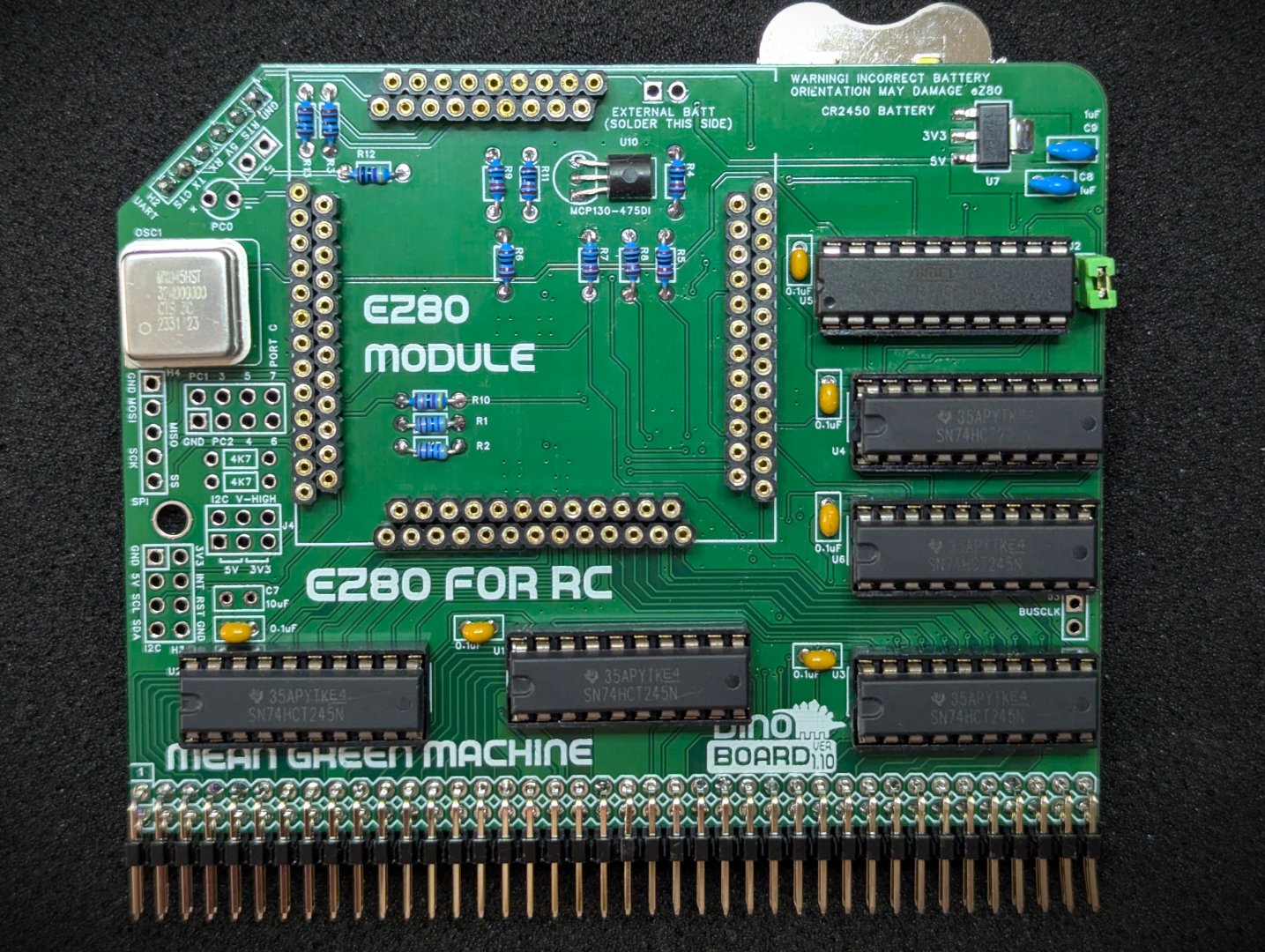
The eZ80 for RC is a CPU Module designed for the RCBus and RC2014™ backplanes.
The eZ80 Zilog CPU is an updated version of Z80 CPU. It comes in a few variations with many on chip facilities in addition to the basic CPU, such as flash ROM, RAM, GPIO and other IO services.
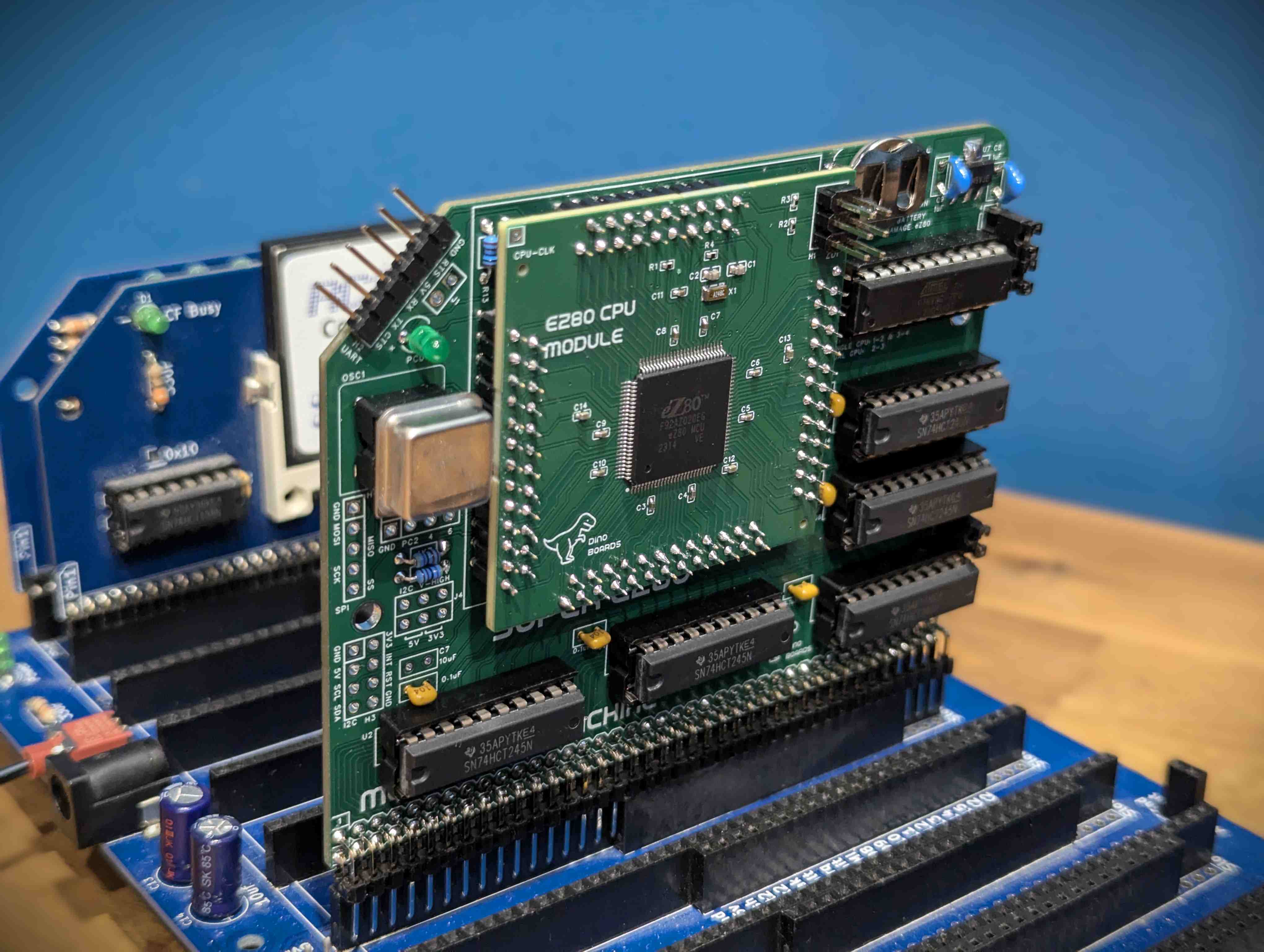
The eZ80 CPU is an enhanced version of the original Z80, largely maintaining compatibility with its predecessor while offering significant improvements. It can directly address up to 16MB of memory and achieves far greater performance per clock cycle due to increased instruction efficiency and pipelining. Additionally, it integrates various on-chip peripherals such as timers, UART, SPI, I2C, and GPIOs, reducing the need for external hardware components.
While the eZ80 might appear slow and limited by today’s standards, it represents, I think, an interesting evolution from the original 1970s Z80 to the modern day embedded microcontrollers.
See the Wikipedia page for basic overview of the CPU (https://en.wikipedia.org/wiki/Zilog_eZ80)
Here’s a video of the eZ80 for RC module running in the RC2014™ backplane with a few retro modules:
The full kits includes everything you need. Including the PCBs, capacitors, IC sockets, connectors, and the various ICs. The included Programmable Logic Device (PLD) will also be flashed with the required logic.
The eZ80 CPU module will come with all the surface mounted components soldered. You just need to solder the PCB pins and a standard 6 pin programming header.
A 20Mhz and an optional 25Mhz crystal to allow you to ‘overclock’ your eZ80.
| Quantity | Component |
|---|---|
| 2 | Right Angle 2x20 Header |
| 6 | 100nF |
| 1 | 10uF Radial |
| 2 | 1uF Radial |
| 2 | HDR M 2.54 1x40 |
| 2 | Shunts 1x2 |
| 1 | 3mm Green LED |
| 1 | 20MHz Crystal Oscillator |
| 4 | 3.4mm 4.7kΩ resistor |
| 2 | 3.4mm 1kΩ resistor |
| 7 | 3.4mm 10kΩ resistor |
| 1 | 3.4mm 47Ω resistor |
| 1 | 3.4mm 470Ω resistor |
| 5 | 74HCT245 |
| 1 | ATF16V8C-7PU |
| 1 | TLV1117LV33DCYR** |
| 1 | BAT-HLD-006-SMT** |
| 1 | MCP130-475DI/TO |
| 6 | 20 POS IC DIP SOCKET |
| 1 | 4 POS SOCKET FOR OSCILLATOR |
| 1 | Interface PCB for RC2014/RCBus Backplane |
| 1 | pre-assembled eZ80 CPU Module |
** The battery holder and 3.3V (TLV1117) DC converter are surface mounted components - but are not hard to solder with a conventional soldering iron.
This kit is designed for RCBus and RC2014™
As per other serial RC2014™ modules, you will need a means to connect the eZ80’s UART to a terminal emulator. The typical FTDI USB converters connected to your PC over USB should suffice.
An eZ80 configured build of RomWBW flashed to the ROM of the external RAM/ROM Module.
Before you can boot your RCBus/RC2014™ system, you will need to have written an image onto the eZ80’s internal ROM. For that you will need a ‘programmer’.
There are 2 options for the programmer. The Zilog’s official programmer (Zilog eZ80 Acclaim USB Smart Cable), available from many hardware suppliers such as digikey or mouser:
An alternative and lower cost option is to use a Raspberry PI Pico. Click here for instructions of setting up a Pi Pico Programmer
V1.11
V1.10
V1.9
Some of the images and videos on this page may include an older revision of the PCB.
The pinout for the SPI interface, prior to revision 1.11 was incorrect. The correct pinout from Pin 1 (at the top) down is:
Reserved for future use. Enable Bus Isolation.
The clock frequency will be the CPU Clock Frequency divided by 4.
The voltage level for operating the I2C bus.
Here are my recommendation for how to approach assembling and soldering the eZ80 Interface PCB and the CPU Module.
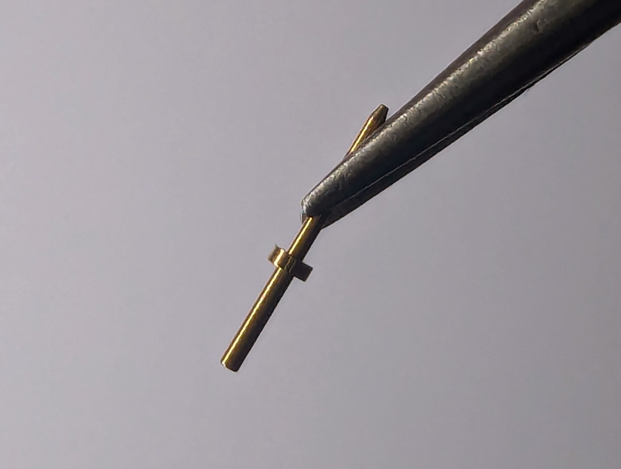
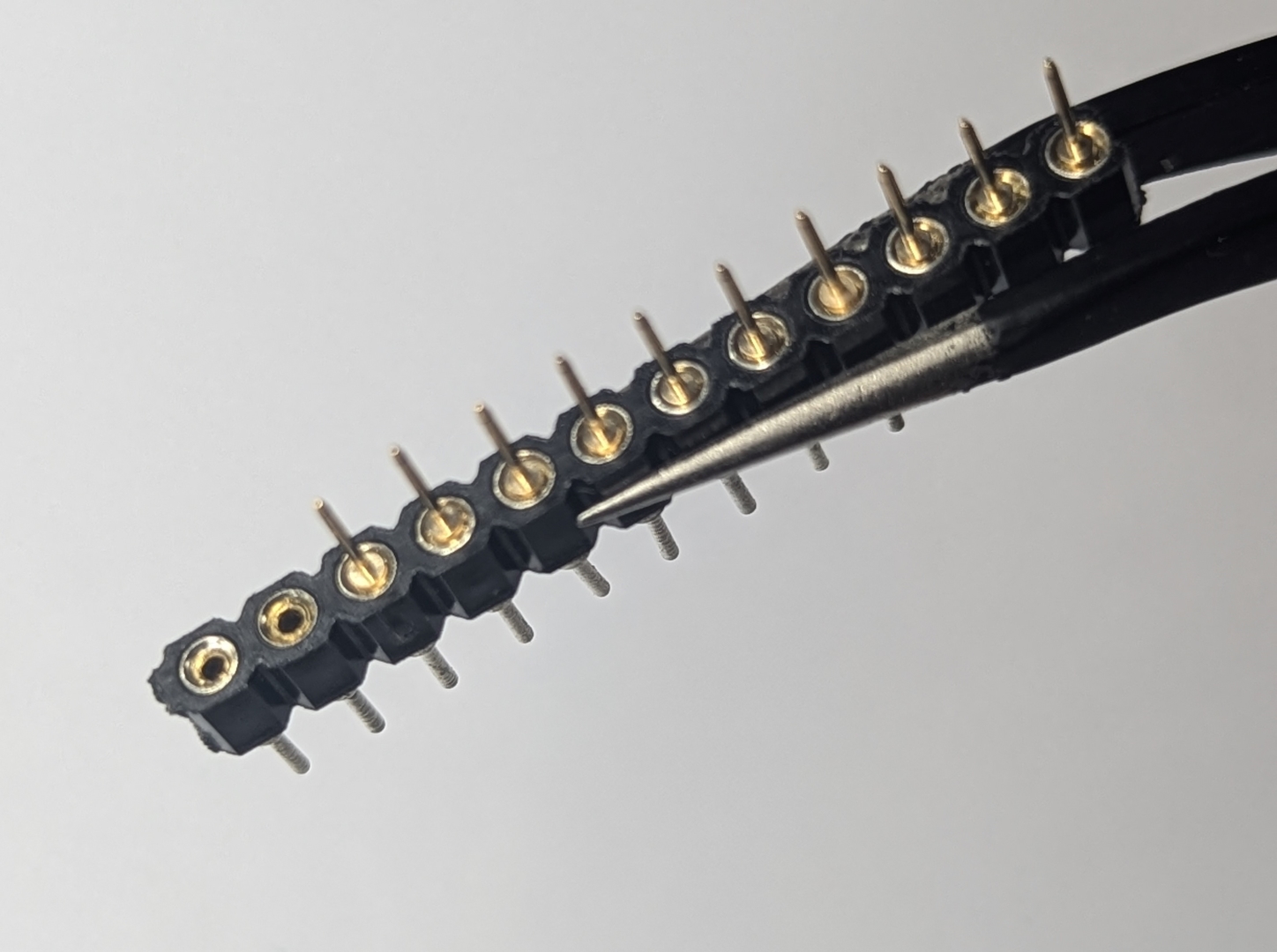
First I start with the PCB pins on the CPU PCB and the associated Round Machine Sockets on the main Interface PCB. The PCB pins require careful attention, as they are quite small, and alignment is important otherwise you may have difficult inserting them into the sockets on the PCB.
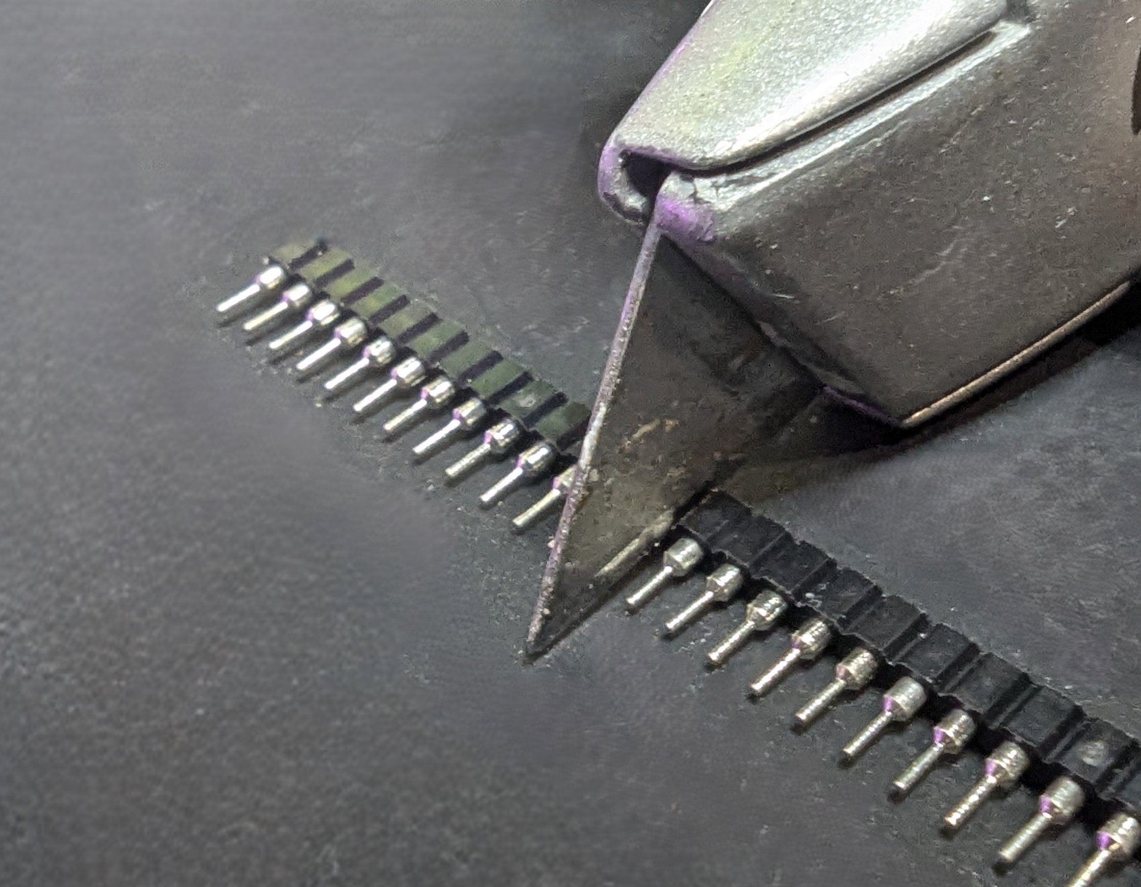
Handle the PCB pins with care, as they can easily slip from your tweezers and flick away in any direction, including towards your eyes.
If installing this module in a case, take into account the available space and select the appropriate type for the 6-pin UART header. You can choose either a right-angle or straight header based on your requirements and preferences.
Please note that this is a kit, produced by a non-expert (me) for hackers, DIYers’ and retro lovers, to tinker with. Please exercise caution and follow good safety practices. You will be working with sharp knives, a hot soldering iron, and small metal components. Be mindful of the risks involved in the build process. I will do my best to answer any questions you may have.
This kit is provided as-is, with no guarantees or warranties. By assembling and using this kit, you acknowledge that you do so at your own risk.