
Code: DB212
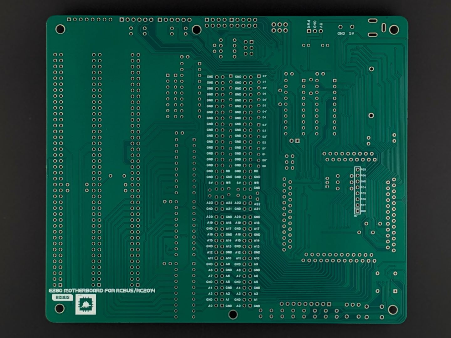
An eZ80 powered base-plane with support for up to 4MB of zero wait state linear RAM and three RCBus/RC2014™ expansion slots.
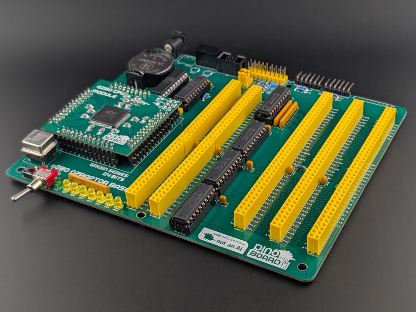
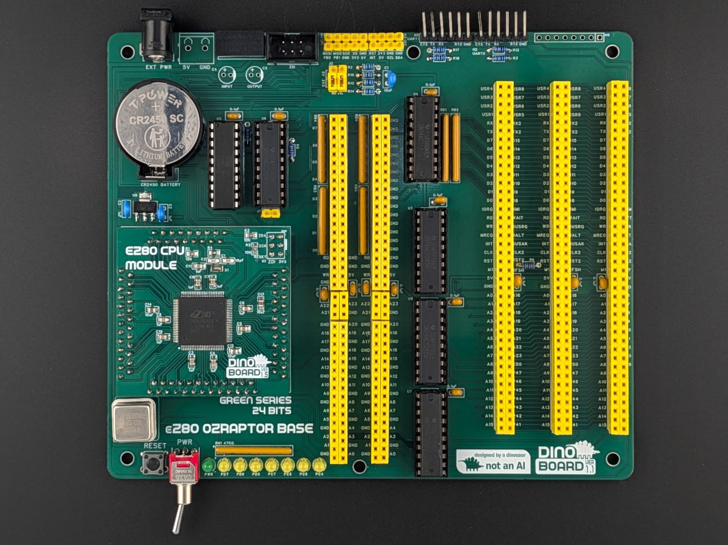
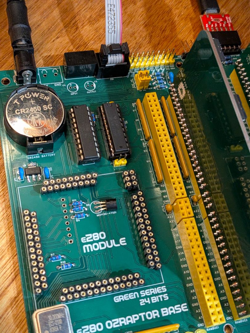
The ozRaptor is a combination of the eZ80 for RC and a powered RCBus/RC2014™ backplane. The 4 layer PCB with the specially designed memory interface allows for higher speed operation.
The eZ80 Zilog CPU is an updated version of Z80 CPU. It comes in a few variations with many on chip facilities in addition to the basic CPU, such as flash ROM, RAM, GPIO and other IO services.
This kit offers a number of features compared to the eZ80 for RC module:
The eZ80 CPU is an enhanced version of the original Z80, largely maintaining compatibility with its predecessor while offering significant improvements. It can directly address up to 16MB of memory and achieves far greater performance per clock cycle due to increased instruction efficiency and pipelining. Additionally, it integrates various on-chip peripherals such as timers, UART, SPI, I2C, and GPIOs, reducing the need for external hardware components.
While the eZ80 might appear slow and limited by today’s standards, it represents, I think, an interesting evolution from the original 1970s Z80 to the modern day embedded microcontrollers.
See the Wikipedia page for basic overview of the CPU (https://en.wikipedia.org/wiki/Zilog_eZ80)
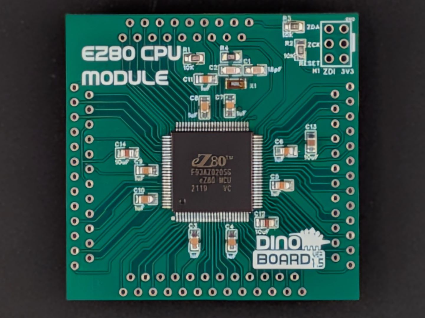
Zilog’s eZ80 CPU is supplied in a small surfaced mounted integrated circuit. This IC is supplied soldered on a small PCB with its various pins (~100) traced to breakout PCB pins. More details of this module can be found here.
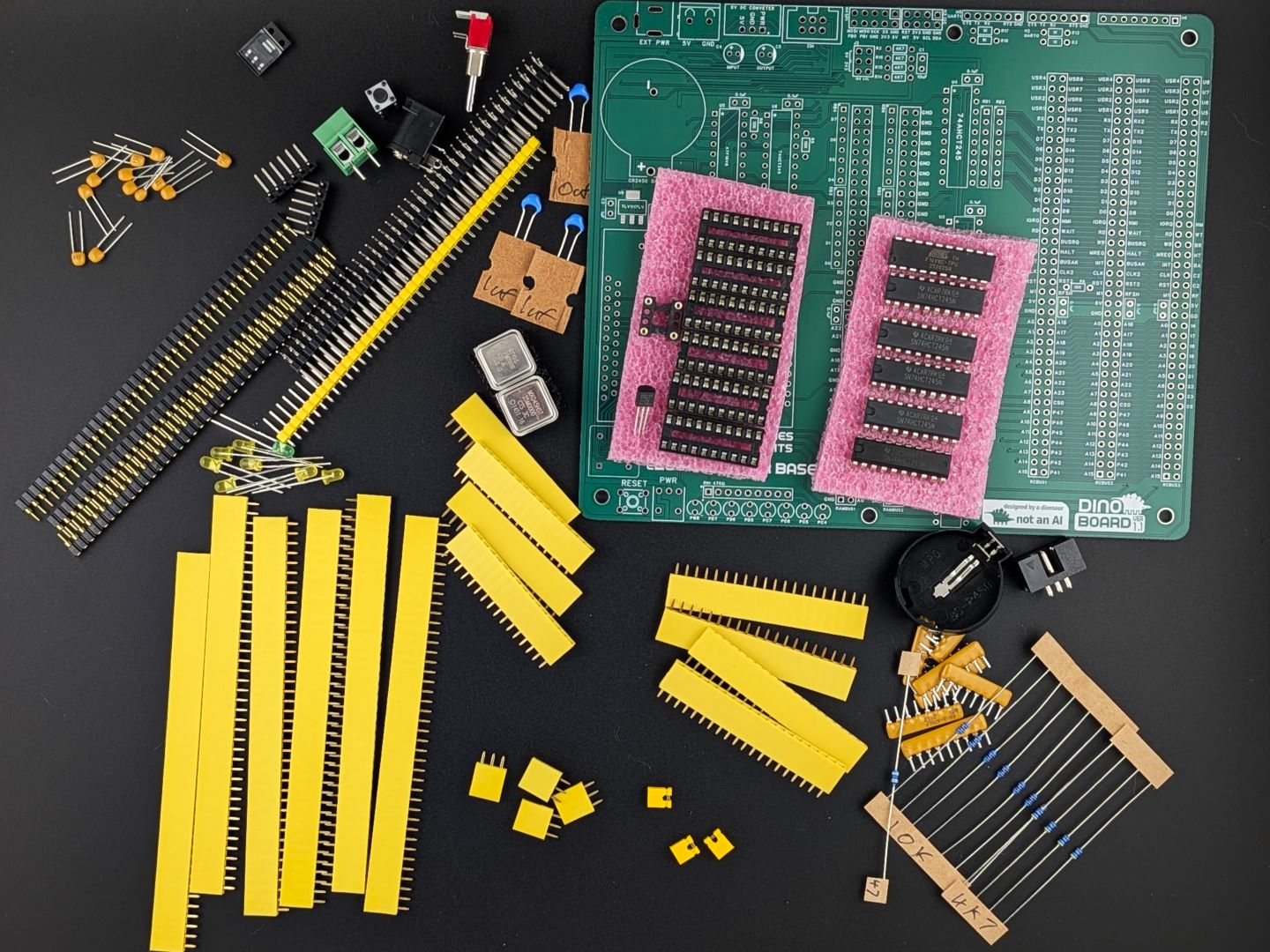
The full kits includes the eZ80 CPU Module, PCB, capacitors, IC sockets, connectors, and the various ICs. The included Programmable Logic Device (PLD) will also be flashed with the required logic.
The eZ80 CPU module will come with all the surface mounted components soldered. You just need to solder the PCB pins.
A 20Mhz and an optional 25Mhz crystal to allow you to ‘overclock’ your eZ80.
The optional high speed memory expansion modules are not included - they are sold separately.
RCBus/RC2014™ expansion modules sold separately.
 |
 |
 |
 |
 |
 |
 |
 |
 |
* Self Source Reference are supplied as a guide only. Please double check, in case of typo or errors in listing.
| Quantity | Component | Self Sourcing* |
|---|---|---|
| 2 | Right Angle 2x20 Header | Digikey: 2057-PH2RA-40-UA-ND Mouser: 649-68020-140HLF |
| 6 | 1x40 2.54mm Male headers | |
| 4 | 1x3 2.54mm Male headers | |
| 4 | 1x20 2.54mm Male headers | |
| 4 | 1x16 2.54mm Male headers | |
| 3 | 1x40 Round Female socket headers | |
| 2 | 1x6 Right Angle headers | |
| 13 | 0.1uF | Digikey: BC5137-ND Mouser: 594-K104K10X7RF53L2 |
| 1 | 10uF Radial | Digikey: FG18X5R1E106MRT06 |
| 2 | 1uF Radial | Digikey: FG18X5R1H105KRT06 |
| 3 | Shunts 1x2 | |
| 8 | 3mm LED | |
| 1 | 20MHz Crystal Oscillator | Digikey: MXO45HS-3C-20M000000 |
| 4 | 3.4mm 4.7kΩ resistor | Digikey: MFR25SFRF52-4K7 |
| 6 | 4x47 Ω resistor network | Digikey: 4608X-102-470LF |
| 2 | 3.4mm 1kΩ resistor | Digikey: MFR25SFTF52-1K |
| 7 | 3.4mm 10kΩ resistor | Digikey: MFR-12FTF52-10K |
| 1 | 3.4mm 47Ω resistor | Digikey: MFR-12FTF52-47R |
| 1 | 8x470Ω resistor network | Digikey: 4609X-101-471LF |
| 1 | DC Barrel Connector | Digikey: PJ-002B |
| 1 | Tactile Switch | |
| 1 | Power Terminal Block (2POS) | Digikey: TB0010-500-02GR |
| 1 | SPDT Toggle Switch | Digikey: 200MSP1T1B2M6QE |
| 1 | 74AHCT245 | Digikey: SN74AHCT245N |
| 4 | 74HCT245 | Digikey: SN74HCT245N |
| 1 | ATF16V8C-7PU | Digikey: ATF16V8C-7PU |
| 1 | TLV1117LV33DCYR** | Digikey: TLV1117LV33DCYR |
| 1 | BS-2450 Battery Holder | Digikey: BS-2450 |
| 1 | MCP130-475DI/TO | Digikey: MCP130-475DI/TO |
| 6 | 20 POS IC DIP SOCKET | Digikey: 2057-ICS-320-T-ND Mouser: 571-1-2199298-6 |
| 1 | 4 POS SOCKET FOR OSCILLATOR | Digikey: A463-ND Mouser: 535-1108800 |
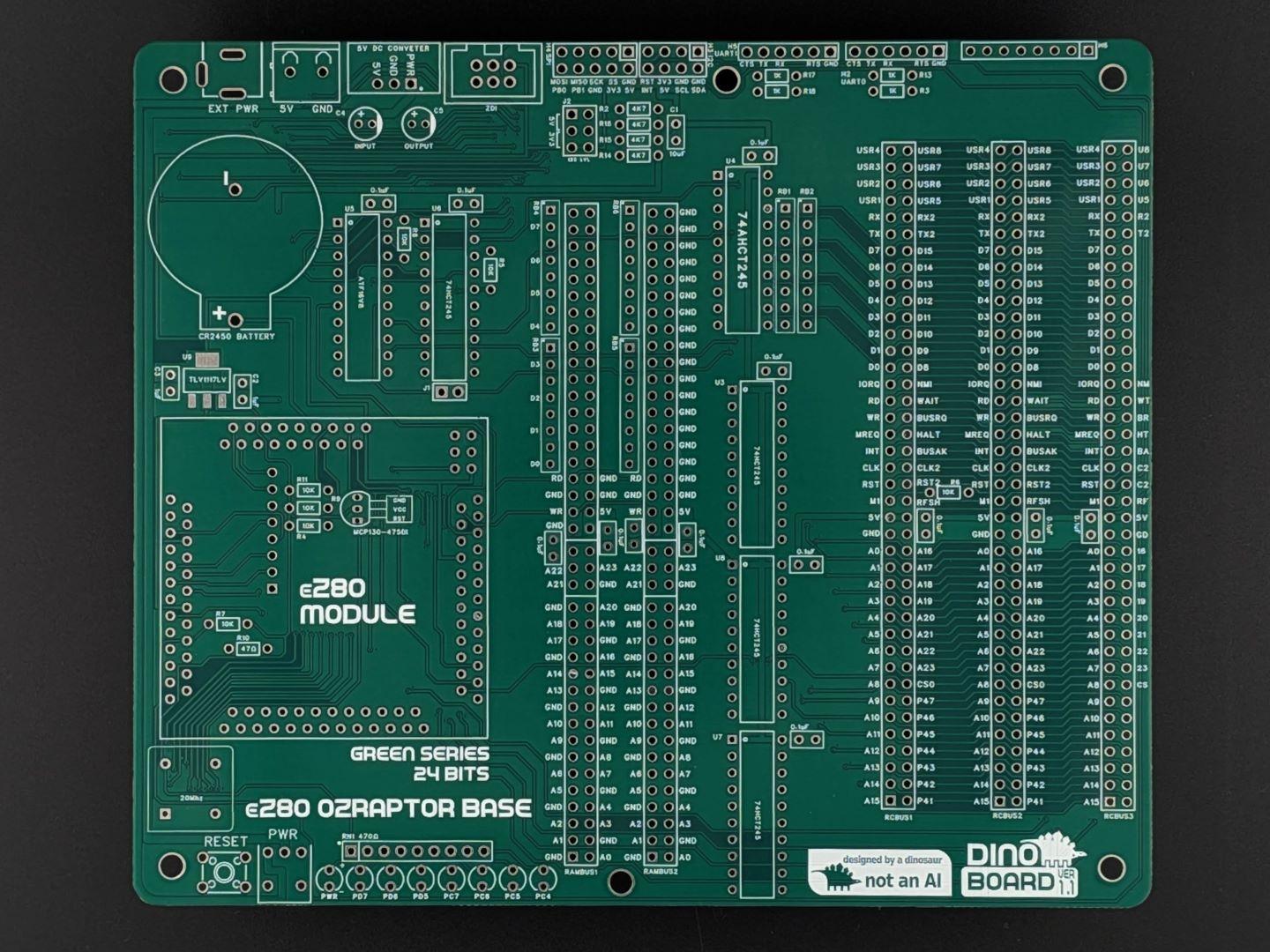
| 1 | 4 Layer PCB | |
| 1 | pre-assembled eZ80 CPU Module | |
| 1 | Compatible DC Converter 12V to 5V | Digikey: 1951-TSR3-2450N-ND Digikey: 3182-LMS78_05-2.0RL-ND |
| 1 | IDC Connector 2x3 | Digikey: BHR-06-VUA |
** The 3.3V (TLV1117) DC converter is a surface mounted component - but is not hard to solder with a conventional soldering iron.
| Quantity | Component | |
|---|---|---|
| 1 | Pi Pico | |
| 1 | PCB | |
| 1 | IDC Connector 2x3 | Digikey: BHR-06-VUA |
| 2 | Slim Header - Male 1x20 | |
| 2 | Slim Header - Female 1x20 | |
| 1 | 6 way idc cable |
There are 2 operating modes: RomWBW booting or Direct USB Storage Booting.
A external RAM/ROM Module. These 2 modules have been tested and verified:
Before you can boot your system, you will need to have written an image onto the eZ80’s internal ROM. For that you will need a ‘programmer’.
There are 2 options for the programmer. The Zilog’s official programmer or the optional Pi Pico Programmer.
Zilog’s eZ80 Acclaim USB Smart Cable is available from many hardware suppliers such as digikey or mouser:
An alternative and lower cost option is to use a Raspberry PI Pico. If you have a Pi Pico handy, you can, via some jumper wires, connect it directly - or you can get the optional eZ80 Pi Pico Programmer kit.
Click here for instructions of setting up a Pi Pico Programmer
Short to enable eZ80 to supply a clock signal to the RCBus/RC2014™ backplane.
(The clock frequency is the CPU’s clock frequency divided by 4)
The voltage level for operating the I2C bus.
Optional header (solder on PCB’s bottom face or bodged to H6)
(PC4..PC7), (PD5..PD6) and ground.

Here are my recommendation for how to approach assembling and soldering the eZ80 Interface PCB and the CPU Module.
The notes regarding soldering the small PCB pins can be ignored if using the conventional Board to Board connectors.
The assembly guide for the eZ80 for RC is worth reviewing. The notes below do detail a different approach to soldering PCB pins.
Recommend this small SMD component is soldered first.
Cut the machine socket strips to the required lengths: 3 strips of 13 pins, 3 strips of 12 pins, and 2 strips of 9 pins. Be cautious when breaking the strips into the required lengths to avoid making a poor cut and losing or exposing the end pin. Using a sharp Stanley knife with some force can help achieve a clean break. Keep the knife straight.
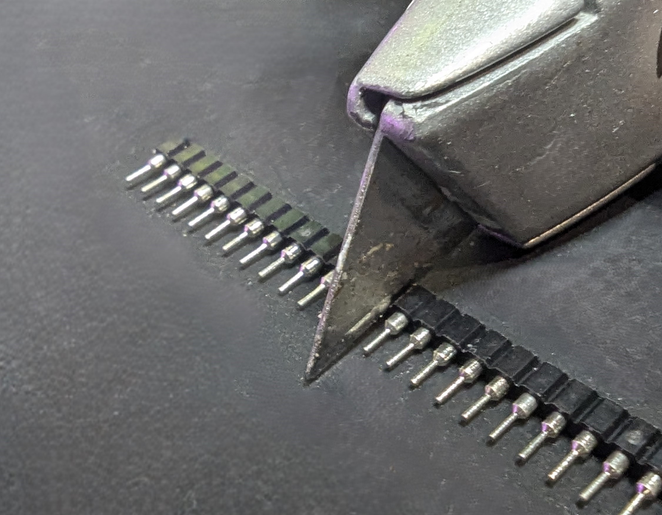
If you are soldering the small PCB Pins, its important to ensure alignment. The recommended approach is to:
first solder the socket into the baseplane - ensuring they are all flat and square.
Using tweezer, insert 2 or 3 pins into the socket (as per NOTE 5). Confirm the PCB pins are gripped within the socket - they should not fall out if its turned upside down.
Place the CPU Module into place. Solder those 2 or 3 pins. Carefully remove the CPU Module, insert some more pins, then repeat the process.
If you attempt to place all pins at one, you may find it very difficult to align the PCB Module over the pins, as tolerances are kept very tight.
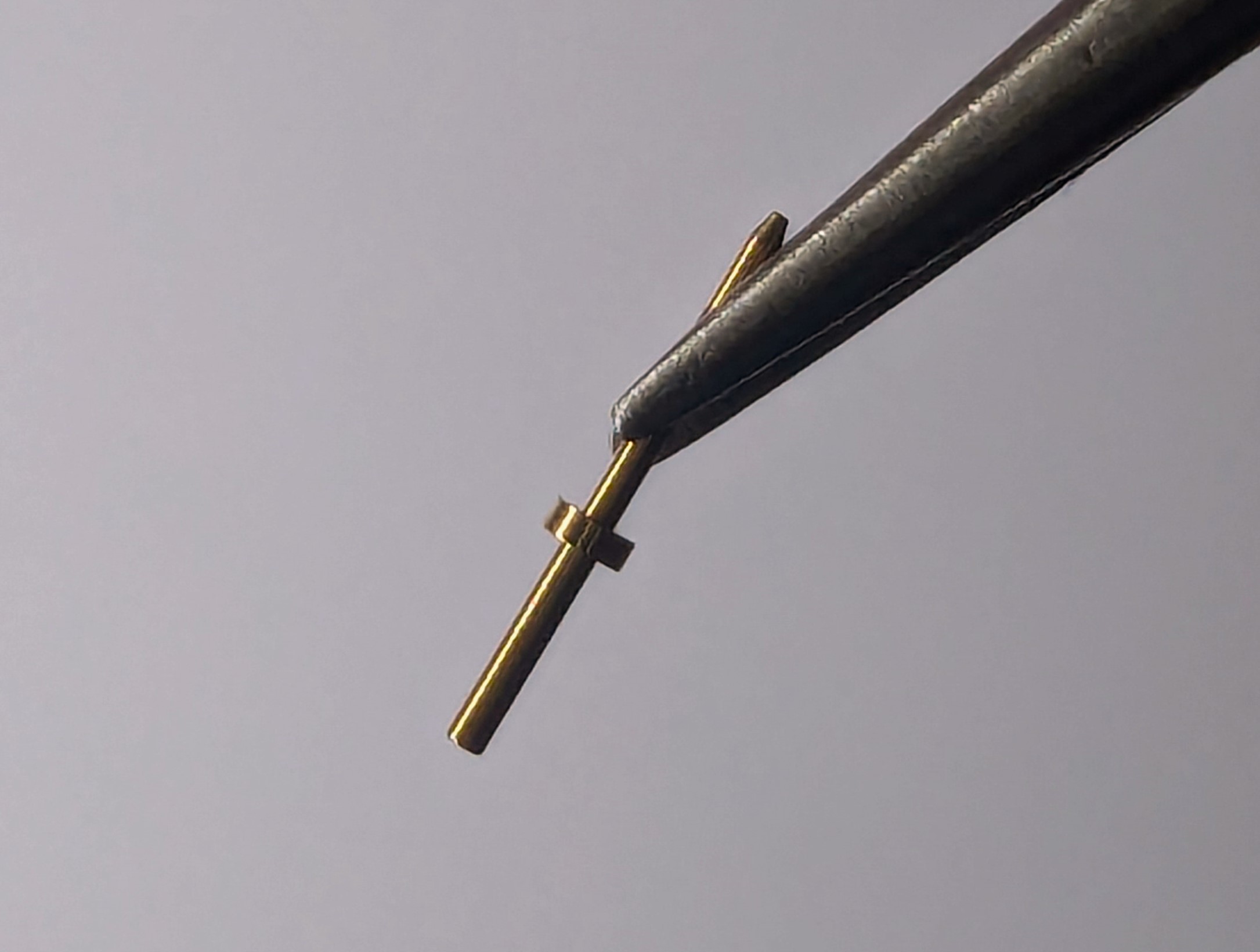
Using precision tweezers, pick up one of the PCB pins and insert the shorter end into one of the sockets. Make sure each PCB pin is fully inserted; you should hear it click into place.
Handle the PCB pins with care, as they can easily slip from your tweezers and flick away in any direction, including towards your eyes.
The ozRaptor board fully supports the programming pins (2x3 connector top right of PCB Module).
If your CPU Module has the programming pins already soldered and facing up, you may want to:
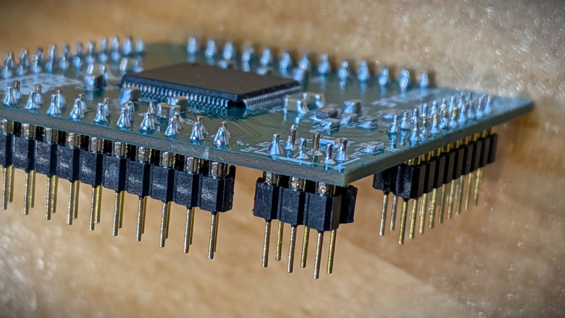
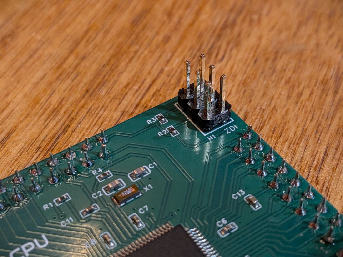
The holes sizes for the programming pins in the eZ80 CPU module are larger, to accommodate a standard header. As such, if you are soldering the small PCB pins, be careful in the application of solder, so at not to ‘solder to the sockets’.
The fast ram headers are comprised of 2 sets of 3 header strips (20 pins, 3 pins and 19 pins). You may want to pay attention to ensuring consistent alignment when soldering.
There is sufficient tolerances should a small mis-alignment occur - but you may find it visually annoying if they are not all straight and consistent.
If you use a fast RAM module to jig the headers into place, make sure you do not attempt to remove the module from the sockets until all connections have been soldered.
After the CPU module and sockets are fully soldered, you can now proceed to solder the rest of the board from lowest height to largest height components.
With kits supplied with the low profile slim 1x20 headers, special care is recommend with the soldering of the female headers to the PCB. There is a risk that when soldering, solder will flow down into the header - and thus prevent a good fit with the associated male headers.
Ensure you solder the 6 pin IDC socket in its correction orientation. See the PCB’s silkscreen layout. Incorrect orientation may result in damaging your eZ80 CPU.
Please note that this is a kit, produced by a non-expert (me) for hackers, DIYers’ and retro lovers, to tinker with. Please exercise caution and follow good safety practices. You will be working with sharp knives, a hot soldering iron, and small metal components. Be mindful of the risks involved in the build process. I will do my best to answer any questions you may have.
This kit is provided as-is, with no guarantees or warranties. By assembling and using this kit, you acknowledge that you do so at your own risk.
 Store